Assignment 3-2D Element Formulation Challenge
OBJECTIVES:
1.Using the crash beam file from the previous assignment, change the run time to 55 ms.
2. Change the number of animation steps during simulation to a minimum of 25 and maximum of 60.
3. Run the base simulation without any modification to element properties.
4. At the end of the simulation, do the energy error and mass error checks and determine whether results would be acceptable.
5. If acceptable, Plot rigid wall forces, internal energy, hourglass energy, contact energy, total energy of the simulations.
6. Change all the shell elements properties to recommended properties, save this as separate, rad files and run the simulation.
7. Follow steps 5 and 6.
8. Create a brief report comparing all the results from steps 5 and 6 for both simulations.
9. Comment whether there is any change in the results and why there is any change in the result.
Recommended properties:
| Parameters | Comment | |
|
Ishell =24 |
QEPH 4 nodes shells are best combination of cost and accuracy. | |
|
Ismstr=2 |
Full geometric nonlinearities (default)with possible small strain formulation activation in RADIOSS Engine. | |
|
Ish3n=2 |
Standard 3 noded shell (C0)with modification for large rotation(default) |
|
| N=5 | Number of integration points set to 5 for accuracy bending. | |
|
Ithick=1 |
Thickness change is taken into account for accuracy. |
|
|
Iplas=1 |
Iterative plasticity for good accuracy. |
Case 1:
First we will perform the simulation without giving recommendate parameters.
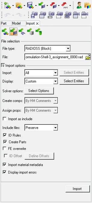
- First import the 0000.rad file in the HyperWorks. Use option IMPORT as shown:
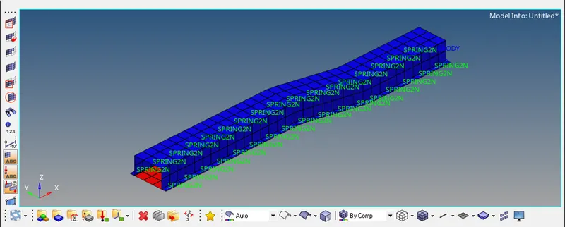
- The actual component is shown below:
- Now we will change the card values one by one
1. Change Run time to 55 ms :
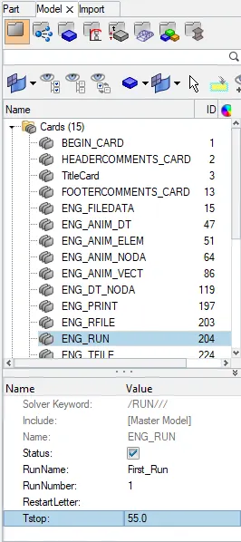
- For that go to the MODEL>CARDS>ENG_RUN
- And change the Tstop as 55. As shown:
2. Change the number of animation steps during simulation to a minimum of 25 and maximum of 60.
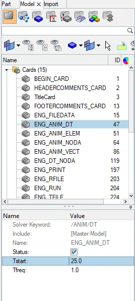
- For that go to the MODEL>CARDS>ENG_ANIM_DT
- And change the Tstart to 25 as shown:
3. Run the base simulation without any modification to element properties.
- For that go to the ANALYSIS>RADIOSS
- After that save the Path where you want to save that file and click on Radioss as shown:

- After that this window will pop-up and it will show all the simulation done as shown:
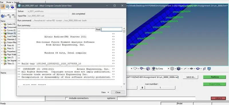
4. At the end of the simulation, do the energy error and mass error checks and determine whether results would be acceptable.
- For this open 0001.out file to get the results as shown:

- So as we can see the TIME is 54.98ms , ERROR is -10.3% and MASS ERROR is 0.1659E-03
- We seen that the energy error is -10.3% and mass error is 0.165e-03. the acceptable value of the energy error is -15 to 5 % and for mass error is 2 to 3 %, means here error value is in the range then its acceptable
- Now we will open animated file, for that go to the HYPERVIEW and open .h3d file, As shown:
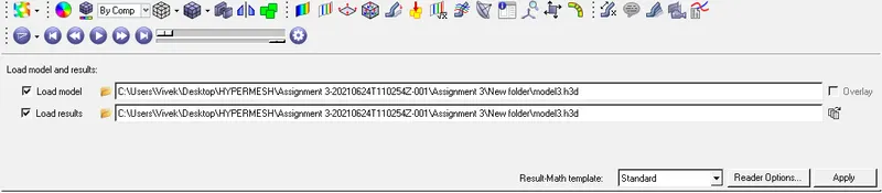
- Now the animated file will look like this:
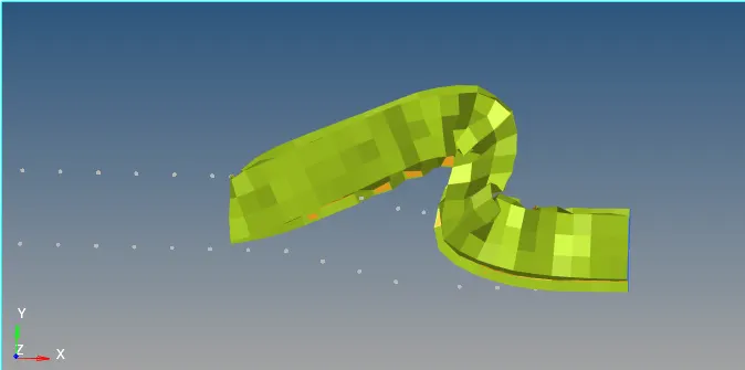
5. Plot rigid wall forces, internal energy, hourglass energy, contact energy, total energy of the simulations.
- For that go to the HYPERGRAPH 2D using spit screen.
- Now open the T01 file to plot the graph. After that we will plot the graph accordingly.
- It will show like this:
- Now ,
1. INTERNAL ENERGY AND KINETIC ENERGY :
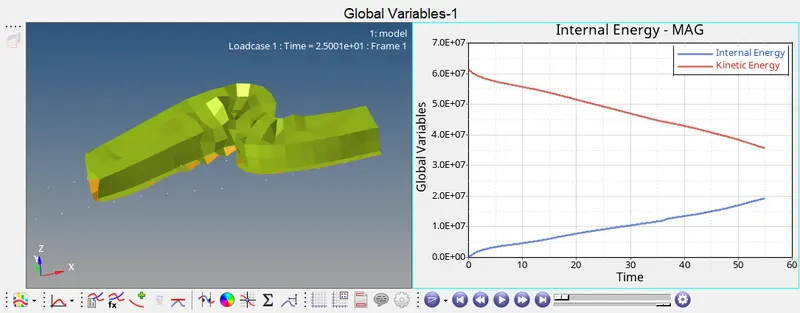
- So as we can see from the graph that , the Internal energy(BLUE) is at zero and start increasing with respect to time. And Kinetic energy(RED) is at maximum and start decreasing with respect to time.
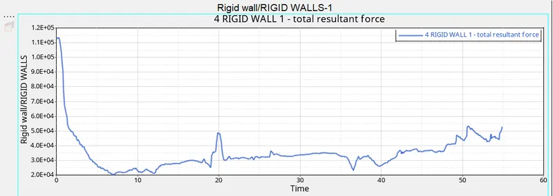
2. RIGID WALL FORCE
3. HOURGLASS, CONTACT ENERGY, TOTAL ENERGY
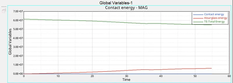
- So as we can see here CONTACT ENERGY is constant and TOTAL ENERGY is decreasing slowly and HOURGLASS ENERGY is increasing slowly.
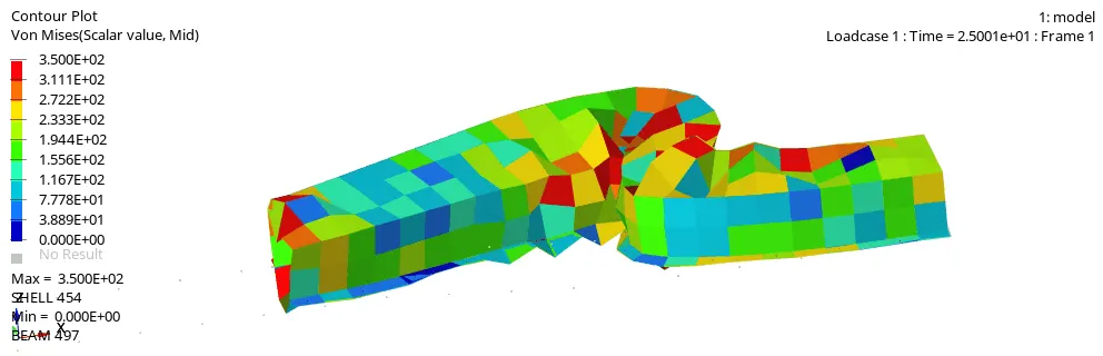
Animation file:
CASE 2:
- In case 2 we will add the recommendate parameters to to cards.
- So first we will import the model and give the parameter the to it.
- We will follow same procedure as we followed for the above case:
1. Change Run time to 55 ms :
- For that go to the MODEL>CARDS>ENG_RUN
- And change the Tstop as 55. As shown:
2. Change the number of animation steps during simulation to a minimum of 25 and maximum of 60.
- For that go to the MODEL>CARDS>ENG_ANIM_DT
- And change the Tstart to 25 as shown:
- Now we will apply the parameter as shown:
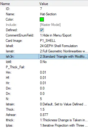
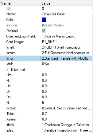
- Now we have given parameters we will follow the same process.
3. Run the base simulation without any modification to element properties.
- For that go to the ANALYSIS>RADIOSS
- After that save the Path where you want to save that file and click on Radioss as shown:
- After that this window will pop-up and it will show all the simulation done as shown:
4. At the end of the simulation, do the energy error and mass error checks and determine whether results would be acceptable.
- For this open 0001.out file to get the results as shown:
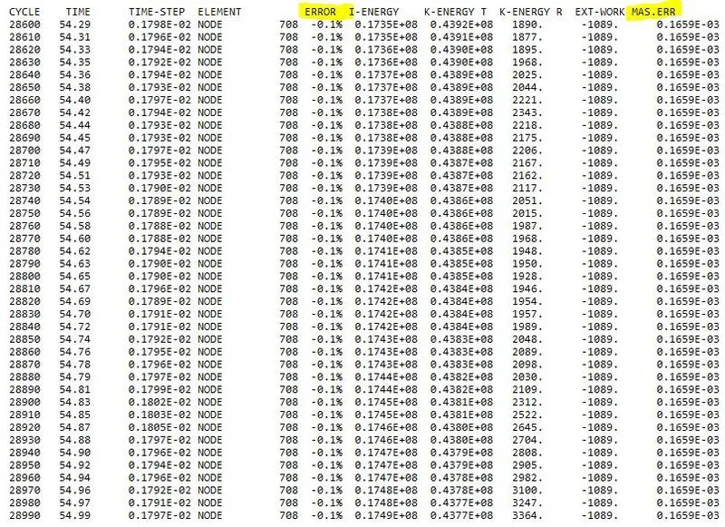
- So as we can see the TIME is 54.99ms , ERROR is -0.1% and MASS ERROR is 0.1659E-03
- So here also We seen that the energy error is -0.1% and mass error is 0.165e-03. the acceptable value of the energy error is -15 to 5 % and for mass error is 2 to 3 %, means here error value is in the range then its acceptable.
- Now if we compare this with the previous resutl we can see that the error is reduced in the Case2 to as compare to Case1
- Now we will open animated file, for that go to the HYPERVIEW and open .h3d file, As shown:
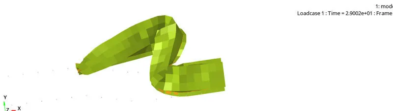
- Now the animated file will look like this:
5. Plot rigid wall forces, internal energy, hourglass energy, contact energy, total energy of the simulations.
- For that go to the HYPERGRAPH 2D using spit screen.
- Now open the T01 file to plot the graph. After that we will plot the graph accordingly.
- It will show like this:
1. INTERNAL ENERGY AND KINETIC ENENRGY :
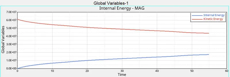
- Here the the graph is same. But The Internal energy is slowly increasing and the kinetic energy is slowly decreasing.
2. RIGID WALL FORCE
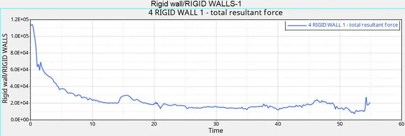
- Now if we compare the RIGID wall graph of Case1 with Case 2 , we can observe that TOTAL RESULTANT FORCE is gradually decreasing in Case 2 and TOTAL RESULTANT FORCE is fluctuating a lil with at every 10ms of time.
3. HOURGLASS, CONTACT ENERGY, TOTAL ENERGY
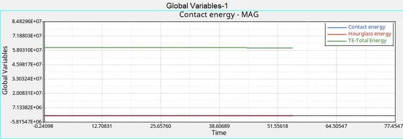
- In this we can see that all the energies are negligible copared to energies in case 1
Animation file:
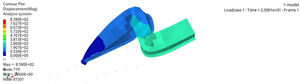
COMPARISON BETWEEN CASE 1 AND CASE 2
- The Animation captured for CASE1 is not natural since elements distort with observable hourglass error while CASE 2 is natural because of using recommended Element properties.
- The %Energy error in CASE 1 is -10.3 % whereas it is just 0.1% for CASE 2.
- Due to change in element property such as ishell and ismstr value we can find out the that there is a good stabilization in hour glass mode in case 2 while comparing to case 1.
- Contact energy is found be 0 Throughout the process on both the simulations.
RESULTS
- All the cases are studied, and the parameters are applied accordingly.
- The required graphs are plotted.
- And the coparison between two cases are done.