Assignment 3-2D Element Formulation Challenge
COMPARSION OF RESULTS WITH THE BASE SIMULATION AND IMPROVED SHELL ELEMENT PROPERTIES
OBJECTIVE
The main objective is to comparison of results with base simulation and improved shell element properties
1.Using the crash beam file from the previous assignment, change the run time to 55 ms.
2. Change the number of animation steps during simulation to a minimum of 25 and maximum of 60.
3. Run the base simulation without any modification to element properties.
4. At the end of the simulation, do the energy error and mass error checks and determine whether results would be acceptable.
5. If acceptable, Plot rigid wall forces, internal energy, hourglass energy, contact energy, total energy of the simulations.
6. Change all the shell elements properties to recommended properties, save this as separate, rad files and run the simulation.
7. Follow steps 5 and 6.
8. Create a brief report comparing all the results from steps 5 and 6 for both simulations.
9. Comment whether there is any change in the results and why there is any change in the result.
PRODECURE
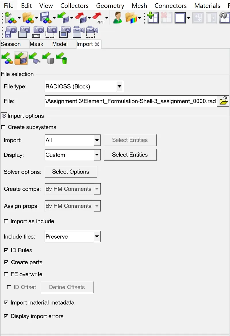
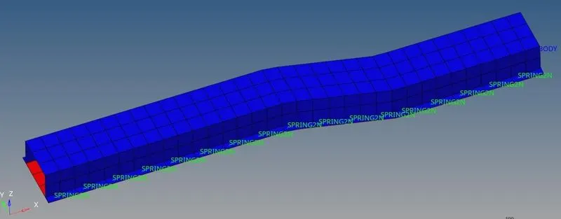
- Importing the crash beam file from the previous assignment by using import solver
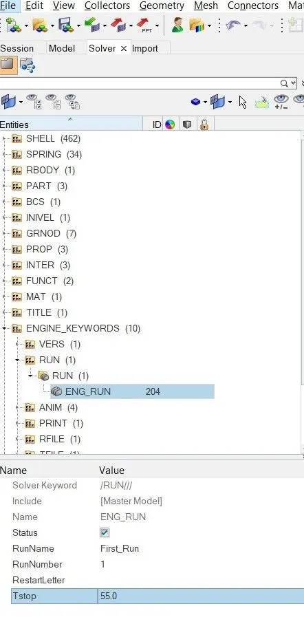
- Using the crash beam file from the previous assignment, change the run time to 55 ms.
- We have to change the run time to 55 ms because run time the simulation .It is the time required to run the simulation so go to solver-engine keywords-ENG_RUN-change tstop as 55 ms
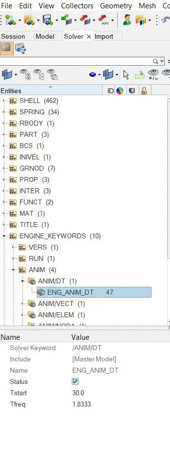
- Change the number of animation steps during simulation to a minimum of 25 and maximum of 60.
- In this they are asking to start the animation file anywhere between times 25ms and 60 ms .So we taken at 30ms . Go to solver - engine keywords - ANIM-ANIM/DT-ENG_ANM_ST-CHANGE T start as 30ms and Tfreq as 1.833
- Run the base simulation without any modification to element properties.
- Actually we have to compare the results of base simulation and improved shell element properties for that reason we have to run the simulation without any modification to element properties .
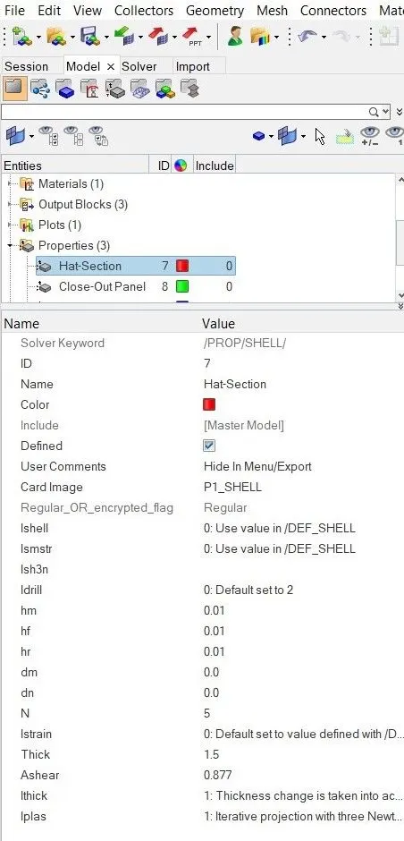
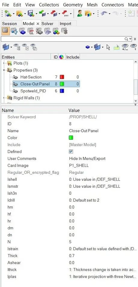
- RUNNING SIMULATION
- We have to run the simulation so go to analysis and click on radioss and a new dialogue box we open and click on the save button to save the file in the respected place and make correction such as export options as all run option as analysis
- At the end of the simulation, do the energy error and mass error checks and determine whether results would be acceptable.
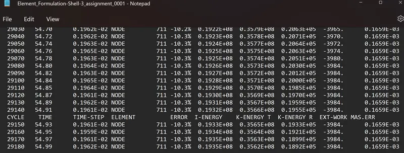
- ENERGY ERROR Basically energy error must be negative and decreasing .The error must be less than -15% at end of computation as per the condition .If the error is below -15% and the result could be acceptable for further ploting of graphs
- If acceptable, Plot rigid wall forces, internal energy, hourglass energy, contact energy, total energy of the simulations.
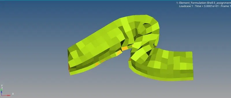
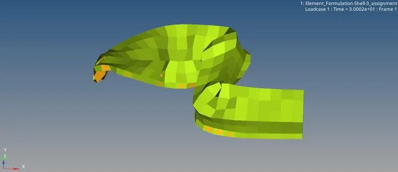
- After accepting the condition we have to plot the various graphs So go the hyperview and import the element _formulation_shell-assignment.h3d file and run the simulation and absorb the deformation of crash beam file . The beam is intially deformed because of varition in the Tstart which is 30ms
- Then go to hypergraph 2d and import the Element_formulation-shell3_assignmentT01 file and plot the required graphs
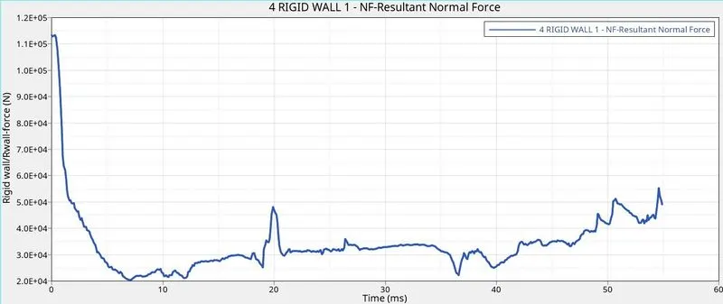
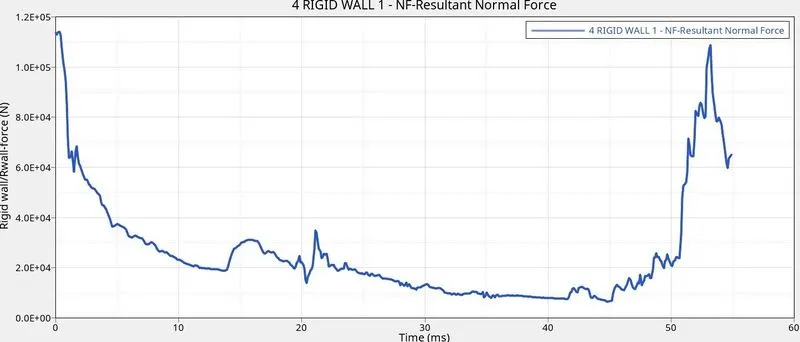
- Rigid walls forces To plot the rigid wall forces - 4 Rigid wall - NF resulatant normal force-apply
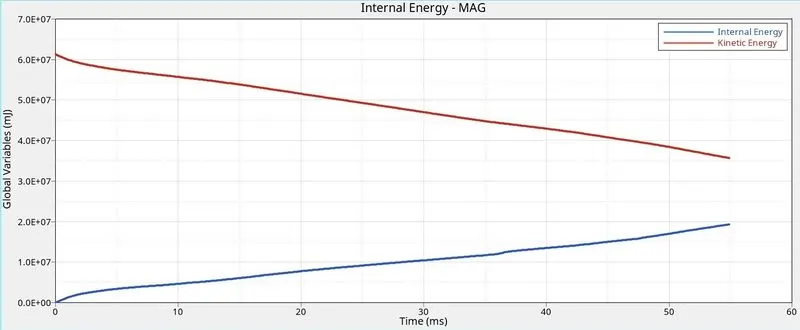
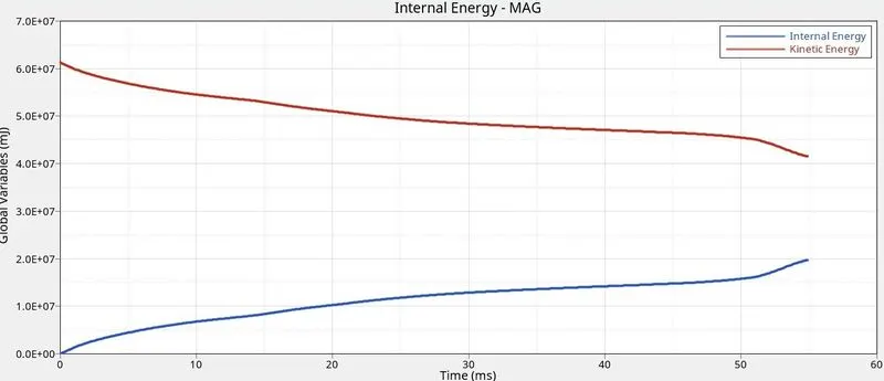
- Internal energy : The internal energy of a system is the energy contained within the system excluding the kinetic energy of motion of the system as a whole and potential energy of the system as a whole due to external force fields
- To plot the graph go to Global variation -Internal energy-and Kinetic energy - MAG
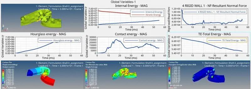
- Internal Energy From the graph the internal energy slowly increases from minimum value of 0.0E+00 to maximum value of 2.0E+07
- Kinetic Energy From the graph the kinetic energy slowly decreases from maximumvalue of 6.1E+07 to minimum value of 3.5E+07
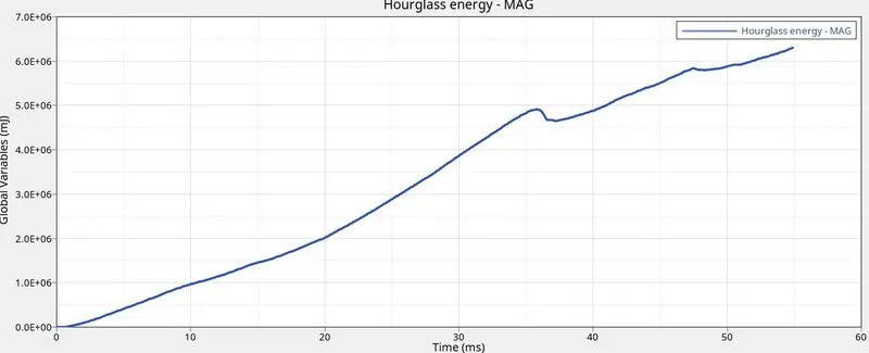
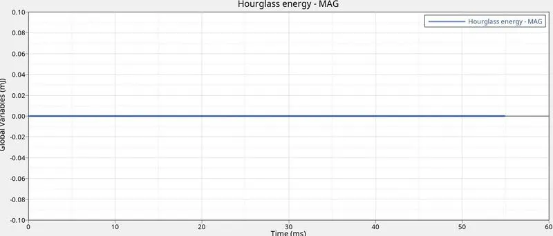
- HOUR GLASS ENERGY For the under integrated shell element displacement and forces may exit for each node of element like the sum of all these forces and displacement give null strain and stress on the inetrgation point of element
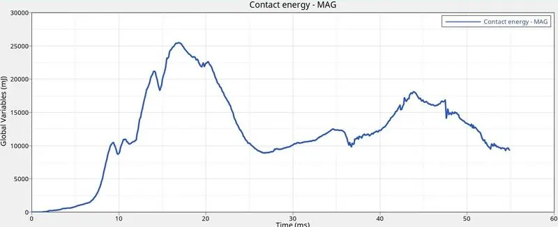
- CONTACT ENERGY For plotting graph go to global variables - contact energy-MAG
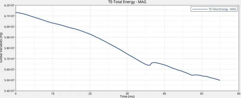
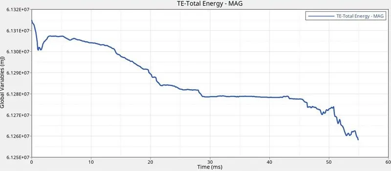
- TOTAL ENERGY For plotting graph go to global variation -Total energy -MAG
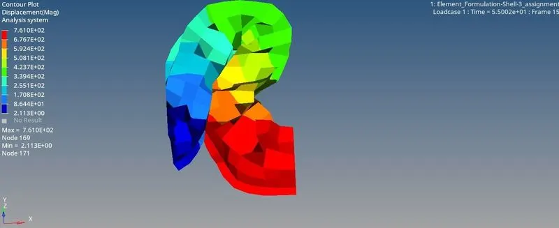
RESULT TYPE Displacement MAG analysis system with a maximum value of 7.610E+02
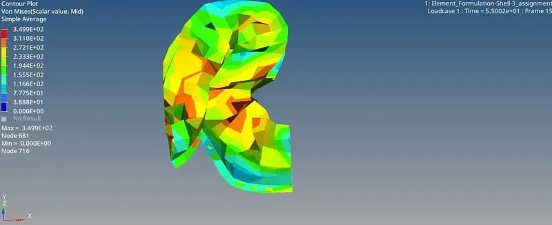
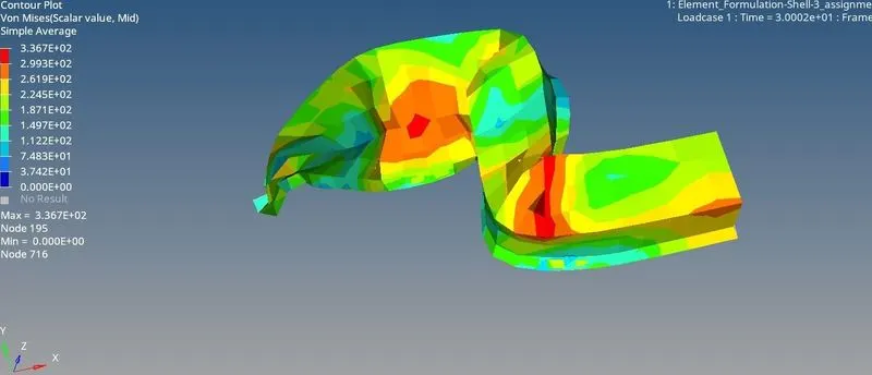
RESULT TYPE Von misses with simple average method .Von misses stress is a value used to determine it a given material will yield of fracture .It is mostly used for ductile materials such as metals
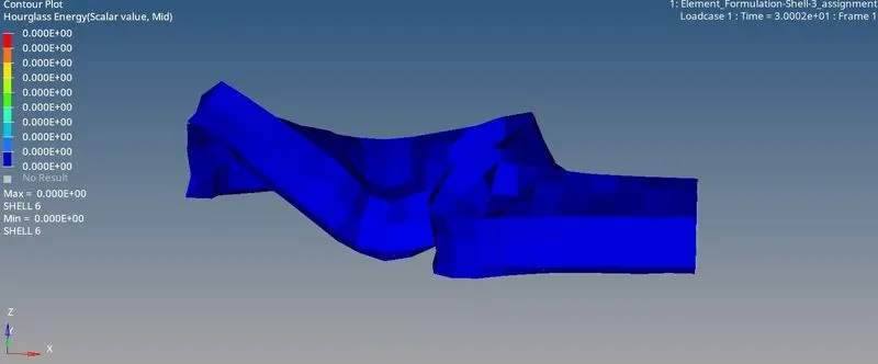
RESULT TYPE Hour glass contour plot element with under integrated point
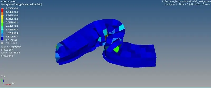
- Change all the shell elements properties to recommended properties, save this as separate, rad files and run the simulation.
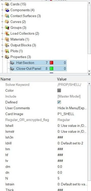
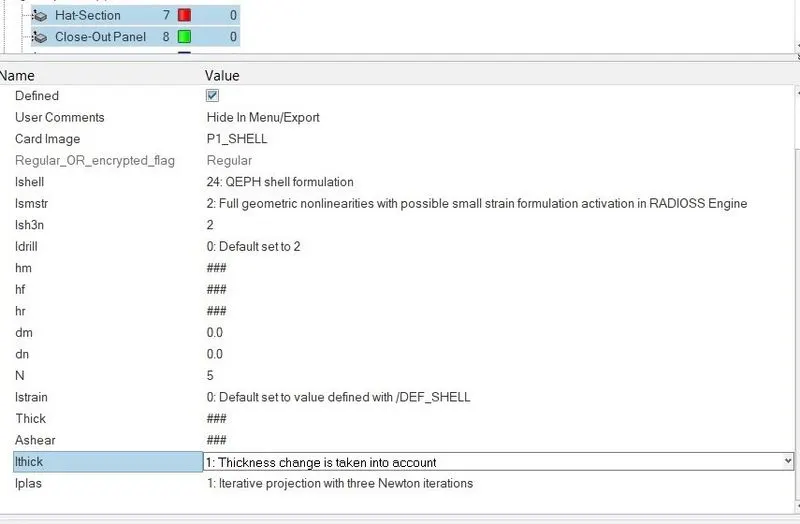
- From above plots we have done our simulation without any change in element properties .Now we have to change all the the shell element properties to recommend properties
-
Parameters Comment Ishell =24
QEPH 4 nodes shells are best combination of cost and accuracy. Ismstr=2
Full geometric nonlinearities (default)with possible small strain formulation activation in RADIOSS Engine. Ish3n=2
Standard 3 noded shell (C0)with modification for large rotation(default)
N=5 Number of integration points set to 5 for accuracy bending. Ithick=1
Thickness change is taken into account for accuracy.
Iplas=1
Iterative plasticity for good accuracy.
RUNNING SIMULATION
We have to run the simulation so go to analysis and click on radioss and a new dialogue box we open and click on save as button to save the file in the repsected place and make correction such as export options as all run option as analysis .
After running the simulation go to file and open Element_Formation-shell-3_assignment_001 file and check for energy error and mass error
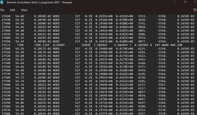
- ENERGY ERROR : So from the above figure at the end of computation the energy error is -0.1% and mass error is 0.1659E-03 .As per the condition the energy error is -0.1% which is below the -15% and the results could be acceptable for further ploting graphs
- Follow steps 5 and 6.
- If acceptable, Plot rigid wall forces, internal energy, hourglass energy, contact energy, total energy of the simulations.
- After accepting the condition we have to plot the various graphs So go the hyperview and import the element _formulation_shell-assignment.h3d file and run the simulation and absorb the deformation of crash beam file . The beam is intially deformed because of varition in the Tstart which is 30ms
- RIGID WALL FORCES
- INTERNAL ENERGY
- HOUR GLASS ENERGY
- CONTACT ENERGY
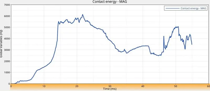
- TOTAL ENERGY
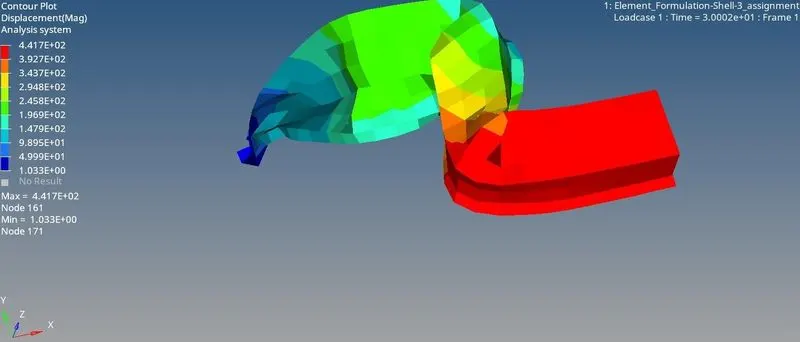
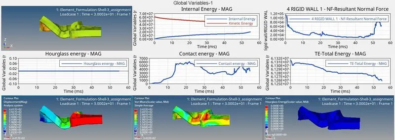
RESULT TYPE Displacement MAG analysis system with a maximum value of 4.417E2+02
RESULT TYPE Von misses with simple average method .Von misses stress is a value used to determine it a given material will yield of fracture .It is mostly used for ductile materials such as metals
RESULT TYPE Hour glass contour plot element with under integrated point
Create a brief report comparing all the results from steps 5 and 6 for both simulations.
WITHOUT MODIFICATION
WITH MODIFICATION
CONCLUSION
- Learnt how to change the element properties , how to run simulation and plotting the various graph
- Conclude that they is a change in the results by changing the element properties
- By the result what we have noticed that the energy error is reduced from -10.3% to -0.1%
- There is no change in mass error and the mass error is independent of changing element properties mass error 0.1659E-03 same for the both the cases without any modification to element properties modification to element properties
- Finally we conclude that the hourglass energy is 0 for modified shell elements properties