Assignment 3-2D Element Formulation Challenge
Objective:
Comparison of results with base simulation and improved shell element properties
1.Using the crash beam file from the previous assignment, change the run time to 55 ms.
2. Change the number of animation steps during simulation to a minimum of 25 and maximum of 60.
3. Run the base simulation without any modification to element properties.
4. At the end of the simulation, do the energy error and mass error checks and determine whether results would be acceptable.
5. If acceptable, Plot rigid wall forces, internal energy, hourglass energy, contact energy, total energy of the simulations.
6. Change all the shell elements properties to recommended properties, save this as separate, rad files and run the simulation.
7. Follow steps 5 and 6.
8. Create a brief report comparing all the results from steps 5 and 6 for both simulations.
9. Comment whether there is any change in the results and why there is any change in the result.
Procedure:
Case 1: (Default properties)
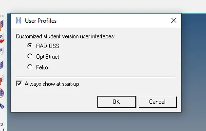
¬Intially open altiar hypermesh and selected the use profile as '' Radioss '' before start it.
¬ Then the import the rad solver file ( starter file) name is runfile_0000.rad
¬In hypermesh - import- file - choose the file whwere it is.
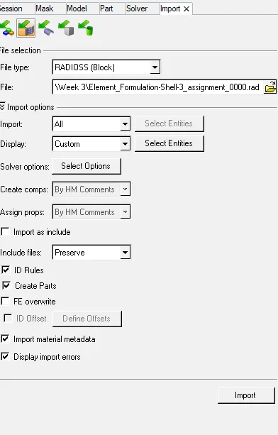
¬ Click the import button.
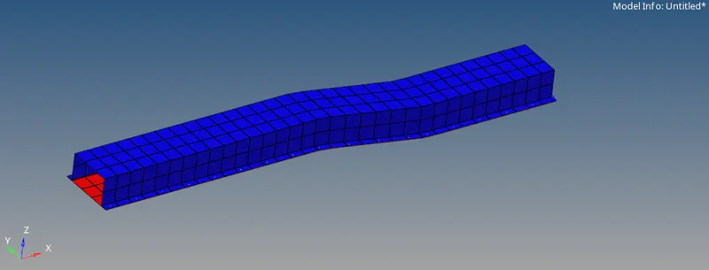
¬After import the working file to assign the run time & animation .
¬Go to solver - engine keyword - run
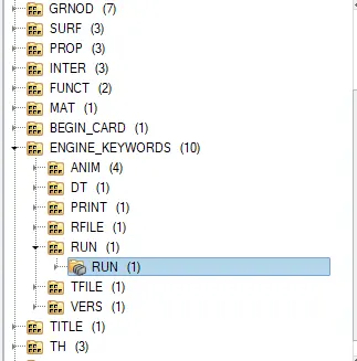
¬Change the Tstop value as 55 as given in question.
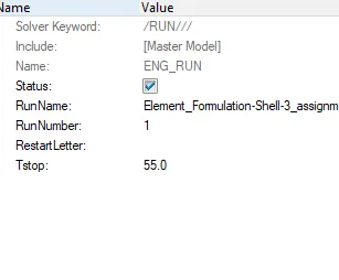
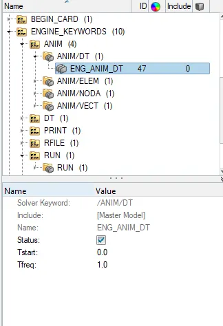
¬Next number of animation file required in question take value as 25 to 60.
¬Tfreq = Time step / number of animation step
¬Now we take as 55 animation step.
¬Take Tfreq value is 1.
¬Then check the properties shell Element formation
¬ In case 1 have to follow the default properties without any changes.
¬Go to model - properties - hat section & close out panel.
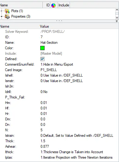
¬Keep it default setting .
¬ Then Run the simulation. Go to Analysis - Radioss.

¬Next choose where the file would be saved.
¬Choose export all option.
¬''-nt 4'' -- Number of threads it 4 process runs simutaneously get result quickly.

¬ Click the radioss button, it start running.
¬After simulation completed get all the file where file saved.
¬ check the total animated file 55 .
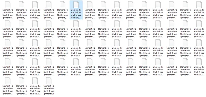
¬Now open the engine file to verify the Tstop and Tfeq value (0001.rad) file.
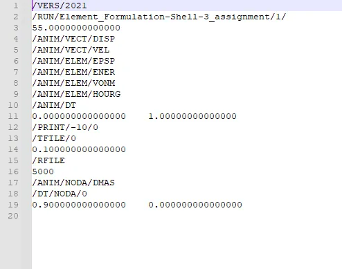
¬ Next step to get the energy error, internal energy, kinetic energy from engine output file (0001.out).
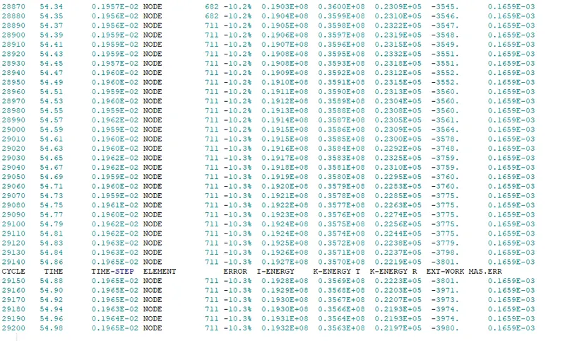
Result of max value and errors:
¬Energy error = -10.3%
¬Internal energy = 0.1932E+08
¬Kinetic Energy = 0.3563E+08
¬Energy error acceptable -15% to 5%.
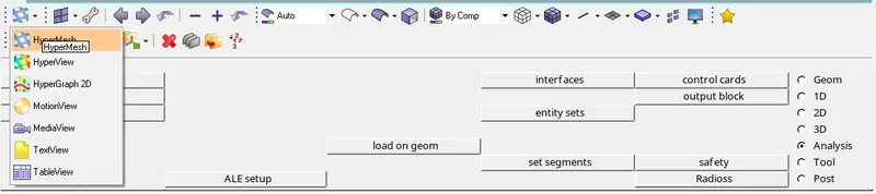
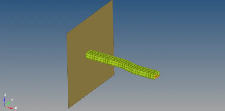
¬Then open the Hyperview window drop down of hypermesh it helps to run the animation.
¬Choose the animation file total animation file is stored in .h3d select it and apply.
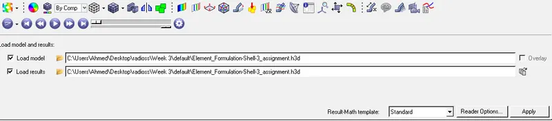
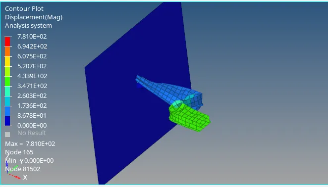
¬import the h3d file below in figure.
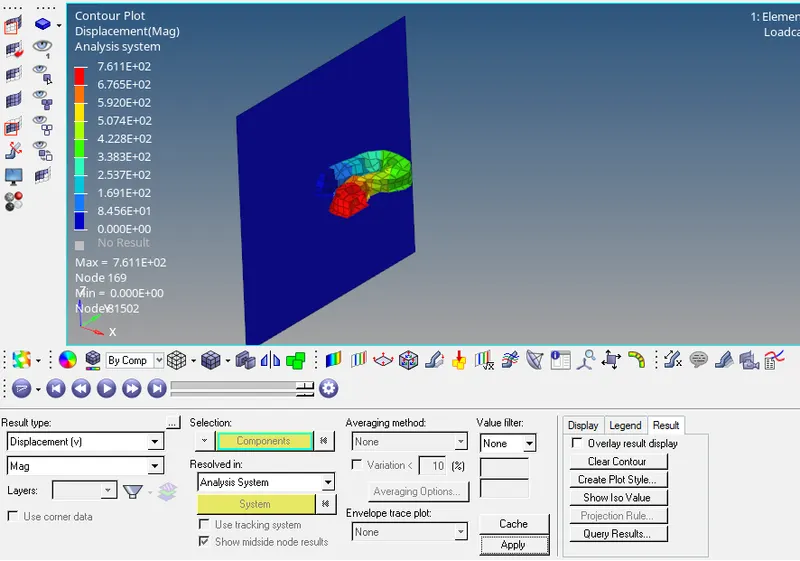
Displacement :
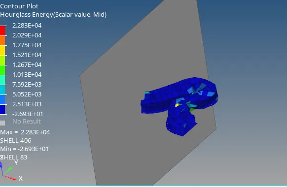
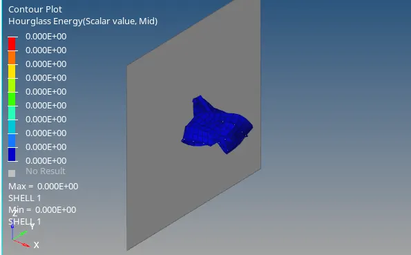
Hourglass energy:
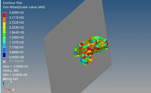
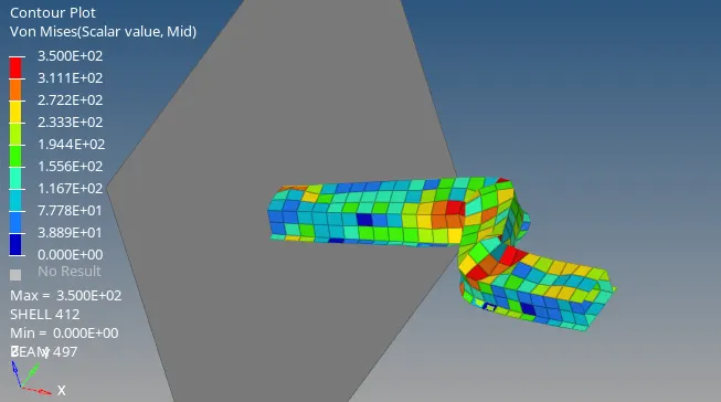
Vonmises stress:
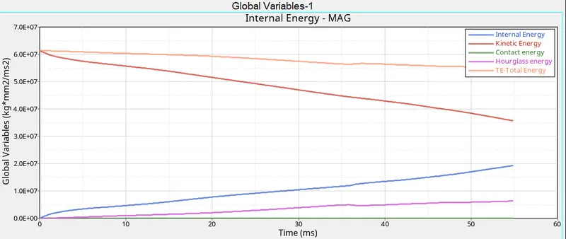
¬Next step view the graph for internal, kinetic, hourglass, contact energy.
¬ Go to hypergraph 2D in drop down in hypermesh.
¬ choose the time history file name as T01 file.
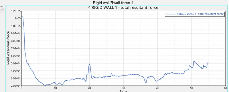
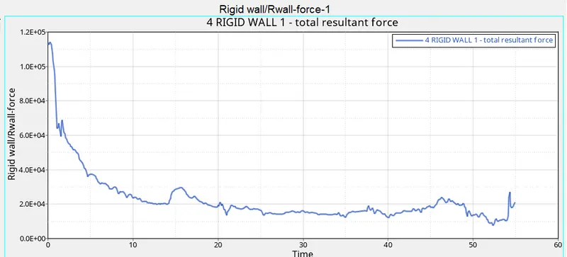
¬Select rigidwall forces and select the total resultant force.

Graph of rigidwall force:
¬Next step plot the graph for internal, kinetic, hourglass, contact energy and toptal energy.
¬Go to hypergraph 2D - select global variables - select energy and click apply.

Energy Graphs:
¬Get all the result from the case 1 Default properties.
Case 2 (Recomended properties)
¬In this case2 is similar to the case 1, only property only change from case 1.
¬Similar to case 1 import file change run time and tfreq value.
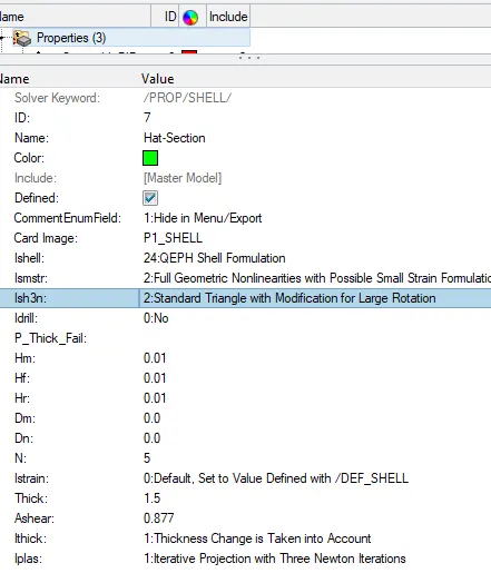
Recommended properties:
| Parameters | Comment | |
|
Ishell =24 |
QEPH 4 nodes shells are best combination of cost and accuracy. | |
|
Ismstr=2 |
Full geometric nonlinearities (default)with possible small strain formulation activation in RADIOSS Engine. | |
|
Ish3n=2 |
Standard 3 noded shell (C0)with modification for large rotation(default) |
|
| N=5 | Number of integration points set to 5 for accuracy bending. | |
|
Ithick=1 |
Thickness change is taken into account for accuracy. |
|
|
Iplas=1 |
Iterative plasticity for good accuracy. |
¬Save this file in diffeent location.
¬This case 2 have engine, output file separetly .
¬Check the animation files
¬ check the engine file.
Get energy error, internal energy,kinetic energy:
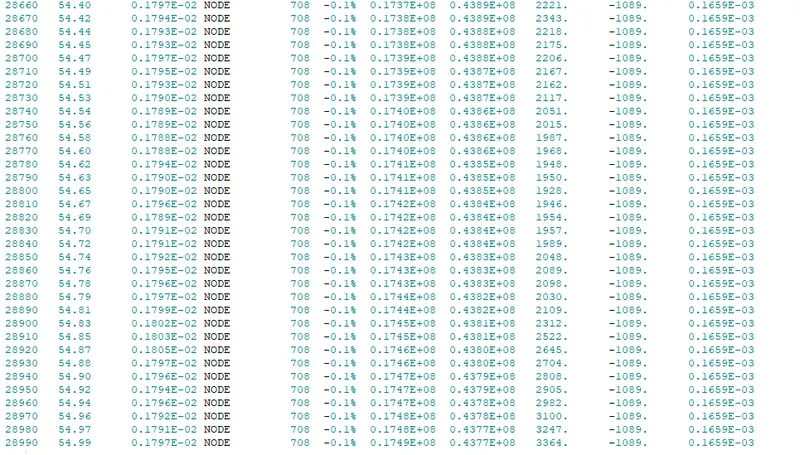
¬Energy error = -0.1.%
¬Internal energy = 0.1749E+08
¬Kinetic Energy = 0.4377E+08
¬Energy error acceptable -15% to 5%.
Displacement:
Hourglass energy:
Von mises stress:
Graph for Rigidwall forces:
Energy Graph:
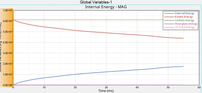
¬ Get all the results from case 2 Recomended properties.
Comarision between case1 and case2 :
| Comparision | CASE1 | CASE2 |
| Max Energy error | -10.3% | -0.1% |
| Max kinetic Energy | 0.3563E+08 | 0.4377E+08 |
| Max internal Energy | 0.1932E+08 | 0.1749E+08 |
| Hourglass energy | Vary hourglass energy.This under integration method, so no physical stabilization. | Constant hourglass energy. This reduce integration method it has physical stabilization. |
| Results | Result are less accurate | Result are more accurate |
Hourglass:
¬ Hourglass is also called as zero energy mode because strain energy deformation not calculated.
¬Hourglass is weird mode deformation due to applied load. it occurs in under integrated method.
¬ No stress produced it reduce the accuracy. Its lead to inaccurate strain and displacement result is inrealistic deformation.
Methods to control Hourglass:
¬Perturbation Method (viscous)
¬Physical Stabilization Method (stiffness)
Perturbation Method:
¬In Perturbation Method using damping to resists the hourglass.
¬Damping its affect only the velocity not forces.
¬Viscous Method recomended for high velocity problems.
Physical Stabilization Method:
¬Stiffness added in material properties
¬This way Hourglass stabilized in QEPH element.
¬Reduce hourglass co-efficient .10 to .03 minimize the stiffness effect
¬It used for low rate problem including crash analysis.
Conclusion:
¬Run the case1 and case2 simulation.
¬Compare the results of case 1 & 2.
Learning outcomes:
¬Learn to property card.
¬Learn to run simulation.
¬Learn to use hyperview and hyper graph