Assignment 3-2D Element Formulation Challenge
Questions:
Comparison of results with base simulation and improved shell element properties
1. Using the crash beam file from the previous assignment, change the run time to 55 ms.
2. Change the number of animation steps during simulation to a minimum of 25 and a maximum of 60.
3. Run the base simulation without any modification to element properties.
4. At the end of the simulation, do the energy error and mass error checks and determine whether the results would be acceptable.
5. If acceptable, Plot rigid wall forces, internal energy, hourglass energy, contact energy, the total energy of the simulations.
6. Change all the shell elements properties to recommended properties, save this as separate, rad files, and run the simulation.
7. Follow steps 5 and 6.
8. Create a brief report comparing all the results from steps 5 and 6 for both simulations.
9. Comment whether there is any change in the results and why there is any change in the result
Answers
We start by importing the required beam file into the solver deck. After which we change the Tfreq and Tstop values
Tfreq = `("total run time")/("no. of animation steps required")`
It is mentioned in the question to change the animation steps to a value between 25 and 60.
I have chosen 40 animation steps, with run time being 55ms, we can now calculate the frequency
Tfreq = 1.375
Tstop = 55
Now we reflect these changes in the cards.
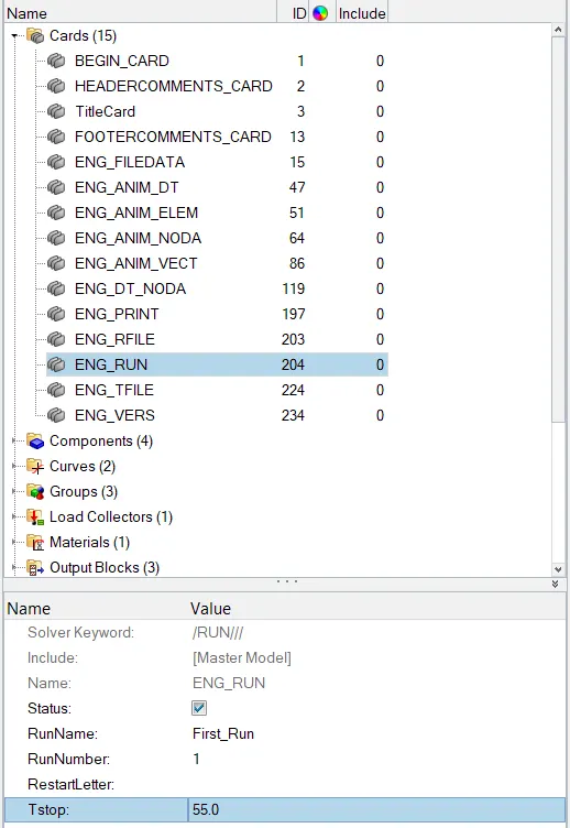
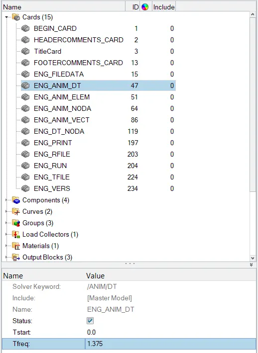
After this, we run the base radioss solver to attain the results.
From the output file opened from the notepad we were able to incur that, the error percentage in case 1(base parameters) = -10.3%
Mass Error = 0.1659E-03
Which is of Acceptable range.
The Plots For internal energy, kinetic energy, hourglass energy, and total energies are plotted below
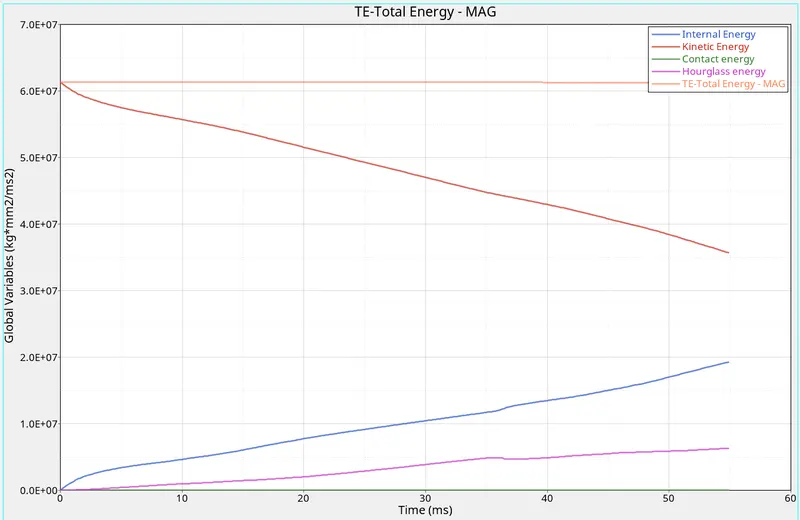 .
.
CASE 2
Keeping these results now we bring about changes in the parameters which can be done in the properties tab in the tree table on the left.
The recommended properties for case 2 are as follows
ishell = 24 (4 noded reduced integration) QEPH shell formation
ismstr = 2 (full geometric Nonlinearities with possible small strain Activation)
ish3n = 2 (standard triangle with modification for rotation)
N = 5
ithick = 1 (thickness change is taken into account)
iplas = 1 (iterative projection with 3 newton iterations)
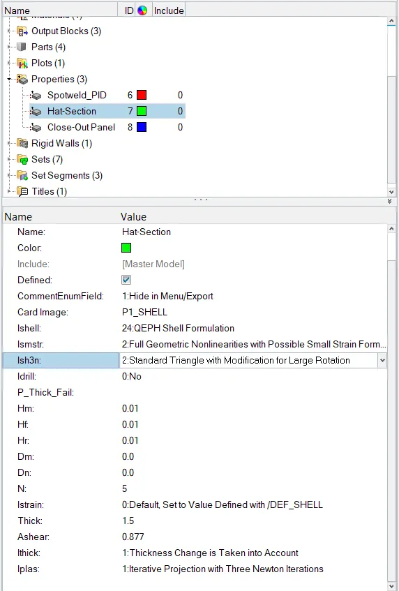
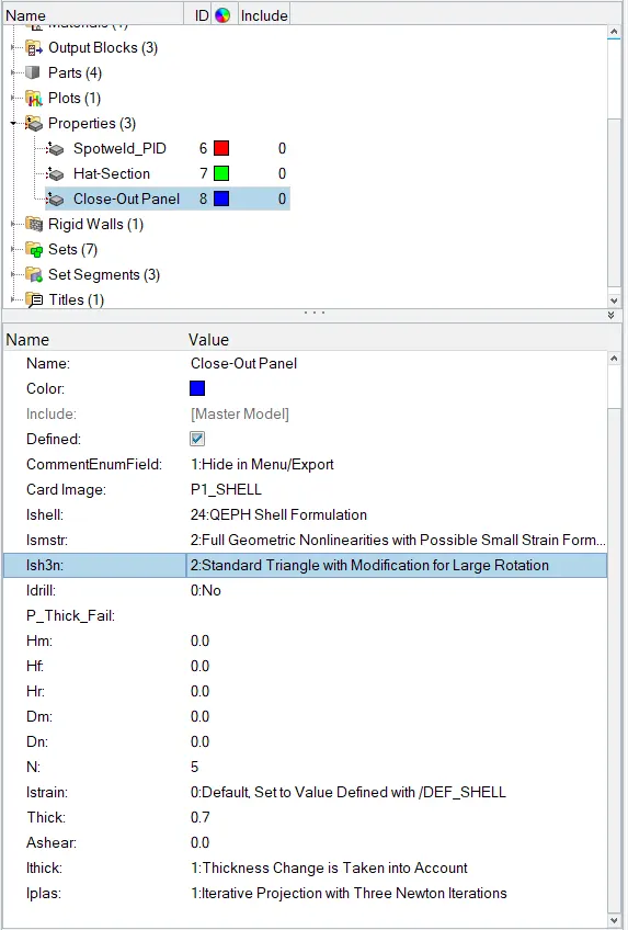
With These parameters, the results are significantly different and better. The error percentage is now= -0.1%.
The mass error remains the same= 0.1659E-03.
The plots for case 2 is below
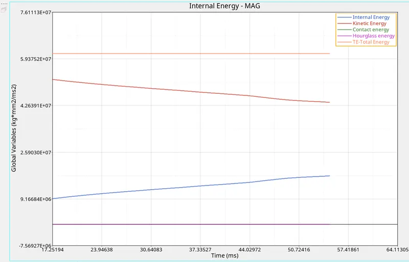
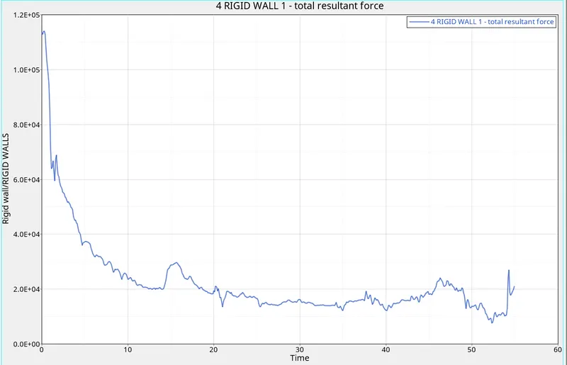
Rigid wall comparison
Case 1
Comparison
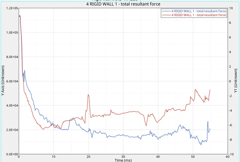
Case 1(in blue)
Case2 (in red)
Conclusion
- What you can see here is that the hourglass energy is Almost negligible on the x-axis. Very low hourglass energy is always preferred for the best results. (case 2)
- The other energies follow a similar trend. The Total energy is more in the first case as there is more Hourglass energy involved.
- The Hourglass energy is reduced in case 2 because of implementing ishell = 24 element formulation which uses a 4 noded element with reduced integration which stabilizes the hourglass energy.
- The total resultant force plots show more irregularities in case 1. This is because no element formulation was applied.
- On the other hand, if you see the plot in case 2 where element formulation was Q24, you can see it is much more stable and has a regular drop of rigid wall forces after the crash.