Assignment 3-2D Element Formulation Challenge
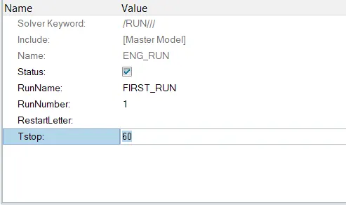
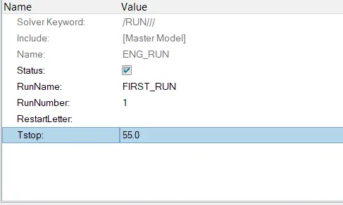
1 ] Changing of the Run Time to 55 ms for crash beam file can be seen below .
- Initially the Run Time was 60 ms which is changed to 55 ms
Before : After :
2 ] For changing the Animation step during the similation wee need to calculate the Tfrequency by the formula as ,
Tfrequency = Siulation Time / Number of Animation steps
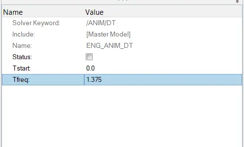
Tfreq. = 55 / 40 ( here I have taken the Animation step = 40 , which is between the minimum 25 to maximum 60 )
hence , Tfreq. = 1.375
this value is then kept in the Anim/DT card as ,
- Now after making the change in the Tfrequency , using the Radioss Solver Analysis is done and simulation is carried out in Hyperview .
- In the Time History File we can clearly see that the Energy error is in between the 0 to -11 % .
- The range of Energy error allowed is about -15 to +5 % .
- And also the Mass error is very less as compair to total mass of the .
- The Mass error should be less than the + 2% of total mass system .
- Hence Our model simulation's results are acceptable .
- Now we can see the Plots of the various parameters which are plotted using the HyperGraph 2D.
- Now By changing the Shell Elemental Properties provided , analysis is done and the Simulation is performed in Hyperview .
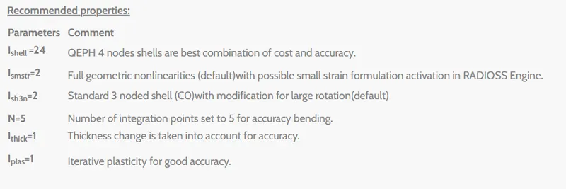
- Provided improved shell elemental properties are ,
- The Results are also plotted using the HyperGraph 2D .
Comparison Between Base simulation results and improved shell elements properties :
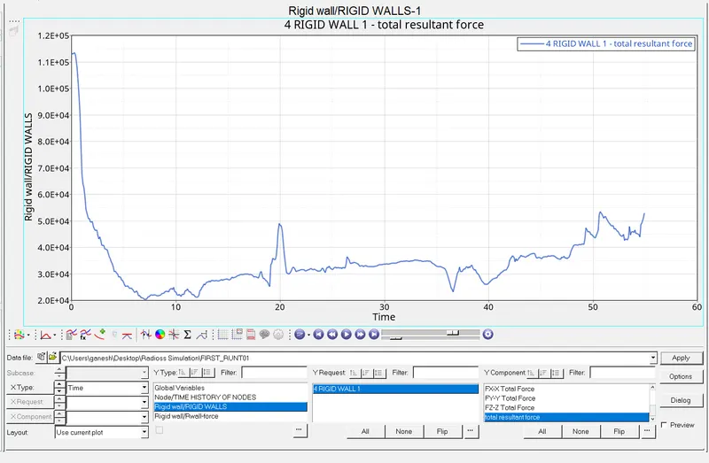
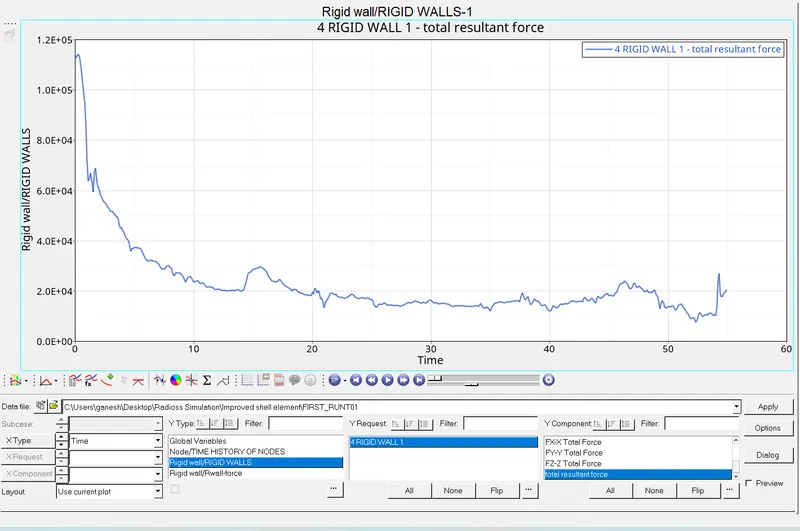
- Above graph shows the Rigid Wall Force - Total Resultant Force of base simulation and after the Improved shell elements properties respectively .
- We can clearly see that the Rigid wall Force _ Total resistance Force against the Time is much more stabalized .
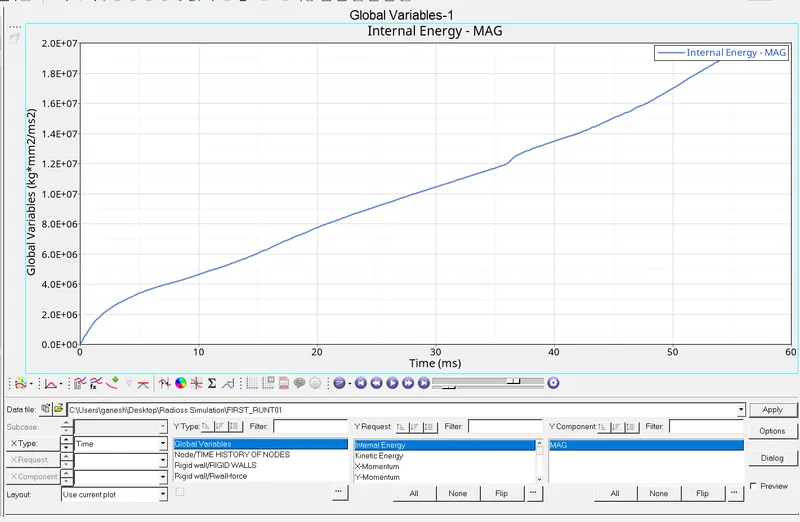
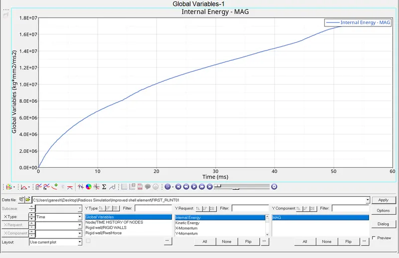
- Above graphs are of the Internal Energy , Where can see that the Internal Energy is Increase Initially at the start of impact but reduces over the total peroid of time .
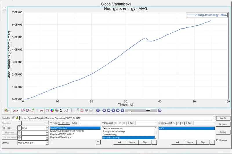
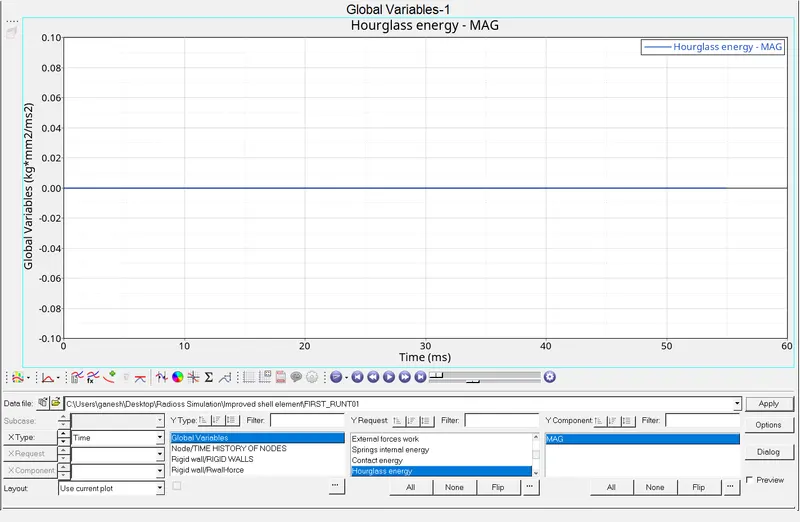
- Above graph shows the Hourglass energy of the base simulation result and the Improved shell elements result .
- We can clearly see that the , Usage of improved Shell elements properties can make the huge difference .
- Usage of the Improved Shell elements property using the Ishell = 24 , which is QEPH 4 nodes Shells are best combination of the Cost and accuracy and the Ishe3n standard 3 noded shell ( CO ) with modification for large rotation .
- This improved Elemental properties reduces the hourgalss energy to almost Zero .
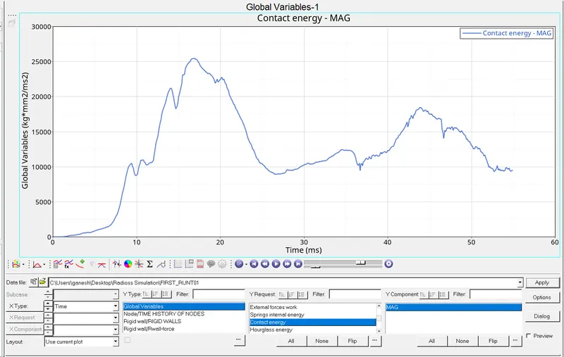
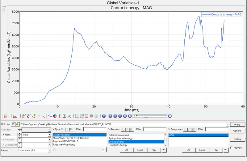
- In the above Graph , we can see that the Contact energy is increases in case of the Improved Shell elements properties than the base simulation results .
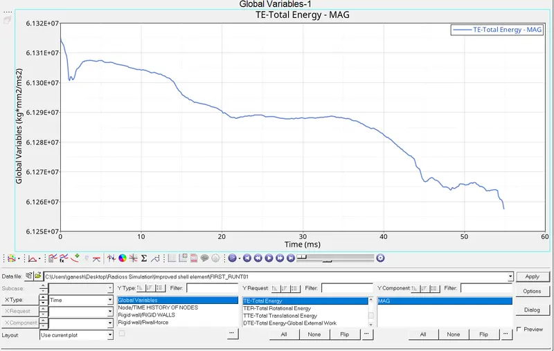
- But For the Internal Energy in case of the improved Shell elements properties ,becomes difficult to control internal energy .
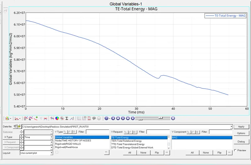
- we can see that the Total Energy more Vibrant .
- In case base simulation result Total energy reduces linearly .
Conclusion :
From Both results we can see that the Hourglass energy is reduced to almost Zero % , becuase the use of the Ishell = 24 ,which is modied 2D shell formulation used to Controll the Hourglass Energy .
Rigid wall forces are stabalized much more in the improved Shell elements properties result than the base simulation results , as the Hourglass energy is reduced ,then contact between the rail and the Wall are improved hence proper stabalization in the Rigid wall forces .