Assignment 3-2D Element Formulation Challenge
To compare the results of the simulation of a beam against the rigid wall with two different 2D element formulations
BASE SIMULATION:
The given radioss file is imported into hypermesh.
The runtime and the frequency had to be changed.The runtime is changed from 60 to 55 in the ENG_RUN card.
The base simulation will run first without any change in properties using the Radioss option in the Analysis tab.
Create a new folder to save the rad files.
In the options enter -nt 4.
After it, the radioss file is run to check whether the energy error and mass error are still within the acceptable range.
The energy error is within acceptable range and the mass error is constant throughout the simulation.
Since the values are acceptable next is to plot rigid wall forces, internal energy, hourglass energy, contact energy, total energy of the simulations with the help of hypergraph 2D
Hyperview is opened to view the simulation animation and the h3d file is imported from the created folder.
The animation shows how the tube is crushed in rigid wall .
next Hypergraph 2D is opened for plotting different energies and T01 file is imported for that.
The internal energy,hourglass energy, constant,kinetic .total energy is plotted in the graph in hypergraph 2D.
The following observations are made from the plot:
Internal energy is increased throughout the graph due to the force on the tube due to the colliding with the rigid wall.
There is an increase in the hourglass energy in the simulation
Contact energy is the same and zero throughout the simulation
there is a decrease in the total energy throughout the simulation.
Another plot is created in Hypergraph 2D for plotting rigid wall forces:
The total resultant forces and the resultant normal forces are plotted as shown below
The maximum and the minimum values of displacement and hour glass energy can be seen using contour plot from hyperview-contour and selecting the components where the crash tube elements are shaded in different colours as show below,
Simulation done with recommended element properties:
Recommended properties:
Recommended properties:
| Parameters | Comment | |
|
Ishell =24 |
QEPH 4 nodes shells are the best combination of cost and accuracy. | |
|
Ismstr=2 |
Full geometric nonlinearities (default)with possible small strain formulation activation in RADIOSS Engine. | |
|
Ish3n=2 |
Standard 3 noded shell (C0)with modification for large rotation(default) |
|
| N=5 | The number of integration points is set to 5 for accuracy bending. | |
|
Ithick=1 |
Thickness change is taken into account for accuracy. |
|
|
Iplas=1 |
Iterative plasticity for good accuracy. |
The given rad file is imported in the hypermesh
The properties of the shell elements are modified according to the reccomended properties
The runtime and the frequency had to be changed.The runtime is changed from 60 to 55 in the ENG_RUN card.
The base simulation is run first without any change in properties using Radioss option in Analysis tab.
Create a new folder to save the rad files.
In the options enter -nt 4.
After it the radioss file is run to check whether the energy error and mass error are still within acceptable range.
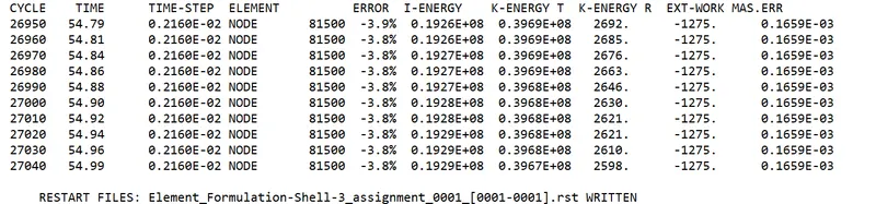
The energy error is within an acceptable range and the mass error is constant throughout the simulation.
Since the values are acceptable next is to plot rigid wall forces, internal energy, hourglass energy, contact energy, total energy of the simulations with the help of hypergraph 2D
Hyperview is opened to view the simulation animation and the h3d file is imported from the created folder.
The animation shows how the tube is crushed in rigid wall .
next Hypergraph 2D is opened for plotting different energies and T01 file is imported for that.
The internal energy,hourglass energy, constant,kinetic .total energy is plotted in the graph in hypergraph 2D
Another plot is created in Hypergraph 2D for plotting rigidwall forces:
The total resultant forces and the resultant normal forces are plotted as shown below
The maximum and the minimum values of displacement and hourglass energy can be seen using contour plot from hyperview-contour and selecting the components where the crash tube elements are shaded in different colors as shown below,
COMPARISON
BASE SIMULATION :
RECOMMENDED PROPERTIES:
ENERGY ERROR AND MASS ERROR:
OBSERVATIONS:
Changes in results are observed after the properties are changed from the default values
- Total energy remains constant after the properties of the shell elements are changed and in the base simulation it is gradually decreasing since the energy error in the recommended properties is 0.1% and in base simulations, it is -10.34%.
- In FEA, the hourglass mode is also known as the "zero-energy mode" because the deformation energy of elements under the hourglassing mode is zero. But the hourglass energy is not equal to zero. Hourglass energy in the base simulation is gradually increasing and in with t recommended properties it is zero and constant throughout the simulation.
- Internal energy is gradually increasing in both cases of the simulations.
- Rigid wall forces have a significant decrease in energy than the base simulation.
- The contour plot shows an increase in the maximum displacement in the elements with recommended properties than the base simulations.
CONCLUSION:
The comparison between the two simulations with different properties showed the necessity to use different properties and choose the right element formulation for problems
T01 FILES:
https://drive.google.com/drive/folders/15btjX_kI0FbjZ29FjOXzkEPbgIyIaZ-4?usp=sharing