Assignment 3-2D Element Formulation Challenge
AIM: To improve the shell element formulation and compare the results using the given model
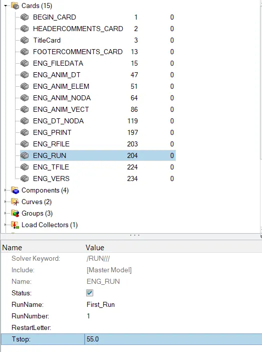
Instruction 1: Using the crash beam file from the previous assignment, change the run time to 55 ms.
Response:
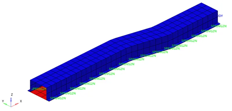
Step -1: This given geometry is imported
Step-2: The run time was changed to 55ms using the ENG_RUN option under the Cards option.
Instruction 2: Change the number of animation steps during simulation to a minimum of 25 and a maximum of 60.
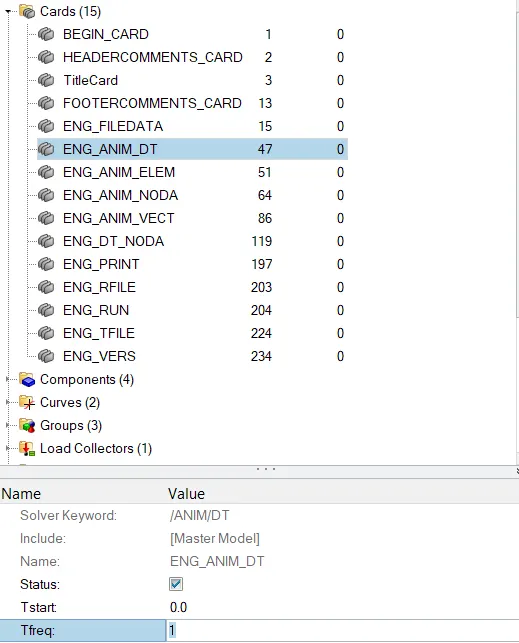
Step -1: The animation steps were assumed to be 55. So, the frequency of the time steps will be 55/55 = 1.
Step-2: To set the frequency of animation, Tfreq was defined to be 1 under ENG_ANIM_DT.
Instruction 3: Run the base simulation without any modification to element properties.
Step -1: Under the Analysis card, Radioss option was chosen to run the simulation using the required simulation settings.

Instruction 4: At the end of the simulation, do the energy error and mass error checks and determine whether the results would be acceptable.
Step-1: After the simulation, 0001.out file was opened to check for the mass and energy error %.
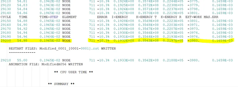
Step-2: Determination of Error %.
It is given that the error % must be negative and decreasing and the error % should be less than 15%.
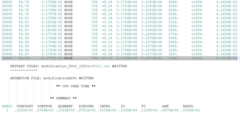
So, from the result, it is clearly evident that the resultant error is -10.3%, which is negative and less than 15%.
Whereas the mass error is 0.1659e-3, which is also within the acceptable limit. Thus, the results obtained after the simulation is acceptable.
Instruction 5: If acceptable, Plot rigid wall forces, internal energy, hourglass energy, contact energy, the total energy of the simulations.
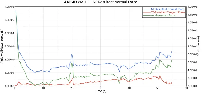
Step-1: To plot the rigid wall forces as a function of time, HyperGraph2D option was utilised.
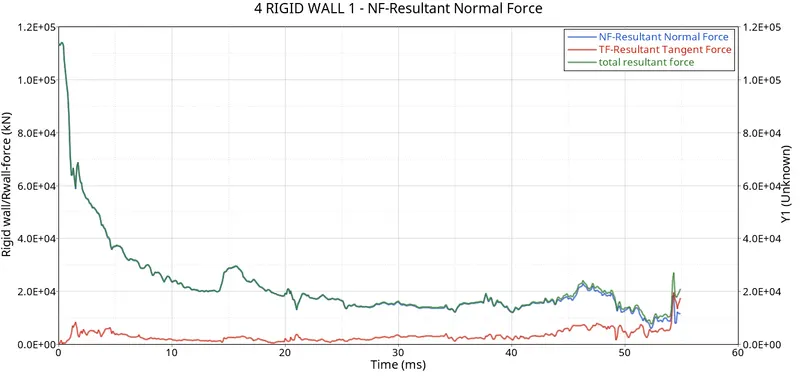
(a) Rigid Wall Forces - the physical phenomenon is not represented accurately using the default element formulation as the total energy is reduced due to the energy losses encountered in the simulation.
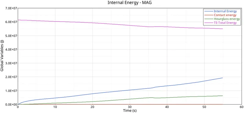
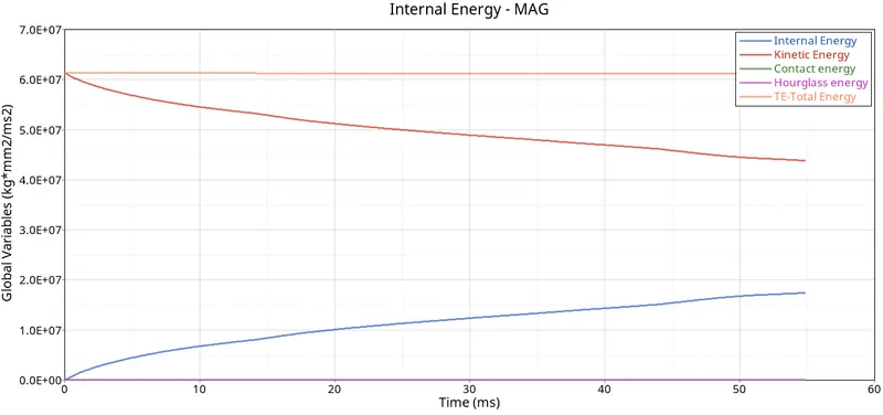
(b) Internal, Hourglass, Contact and Total Energy plots - In the energy plot, prominent losses due to hourglass in observed as Q4 elements determine Hourglass energy using perturbation method and the energy losses is approximately observed to be about 10%. Enhanced element formulation and more integration points inclusion will make the simulation more stable and energy-efficient.
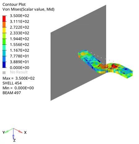
Von-Mises Stress Contour - maximum stress of 350MPa is predicted from the simulation.
Instruction 6: Change all the shell elements properties to recommended properties, save this as separate, rad files and run the simulation.
Instruction 7: Follow steps 5 and 6.
Determination of Error % (Comparision)
It is given that the error % must be negative and decreasing and the error % should be less than 15%.
So, from the result, it is clearly evident that the resultant error reduced to -0.1%, which is negative and less than 15% on the application of shell elemental properties.
Whereas the mass error is 0.1659e-3, which is also within the acceptable limit. Thus, the results obtained after defining the shell elemental properties in the simulation generated better results in comparison to the previously simulated results.
Internal, Hourglass, Contact and Total Energy plots - utilisation of QEPH24 elements produce better results as compared to Q4 elements. The losses due to Contact and Hourglass are minimum. It is imperative to note that, the hourglass energy has been brought down from 10% to about 0.1%, which is due to the selected elemental formulation i.e. QEPH24 which has an integrated hourglass control mechanism.
Rigid Wall Forces - the physical phenomenon is accurately represented.
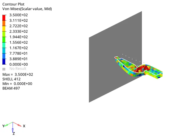
Von-Mises Stress Contour - maximum stress of 350MPa is predicted from the simulation.
CONCLUSION
- In comparison, it was determined that QEPH 4 node shell elements predicted the crash energy more accurately with 0.1% energy ERROR.
- There was on change in maximum von-mises stresses in the system.
- The error in mass addition was negligible in both simulations.