Assignment 2-RADIOSS Engine File Editing & 3D Meshing Challenge
Assignment 2
Objective
- To 3D mesh the given components
- To modify the .rad file and calculate timestep
Procedure
- Given Density =0.0078 g/mm3
Youngs Modulus E=210Gpa - Speed of Sound = `sqrt (E/rho)`
- Applying the values to the formula above, we get the speed of sound as 164.08 mm/s
- The length of the rail is 1000mm
- The time is taken for sound to travel across the rail = `l/sqrt(E/rho)`
- This gives us a value of 6.094 seconds
- To calculate tfreq for 20 animations the formula is= 6.094/20 =0.3047
- The desired changes can either be directly added to the .radfile but care needs to be taken that the number of digits remains the same
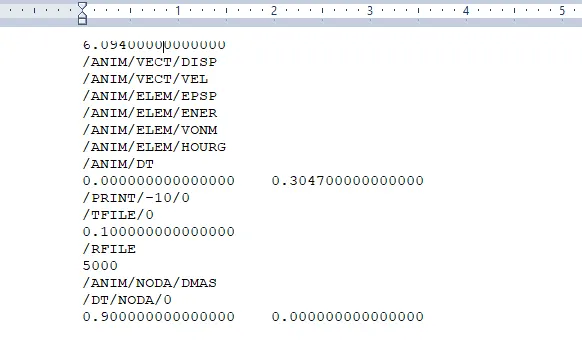
Figure 1
- An alternate method is to modify the files using hypermesh
- Import the .000rad file using import solver deck.
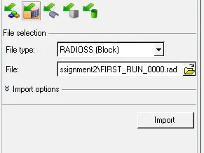
Figure 2 - Make the necessary changes in ENG_ANIM_DT,ENG_RUN and ENG_PRINT Cards
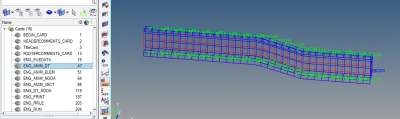
Figure 3
- After the changes are made,it is necessary to export it to a folder
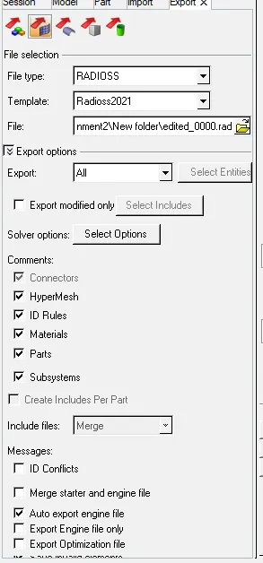
Figure 4
- After exporting,open the .0001 rad file in notepad to verify the changes.
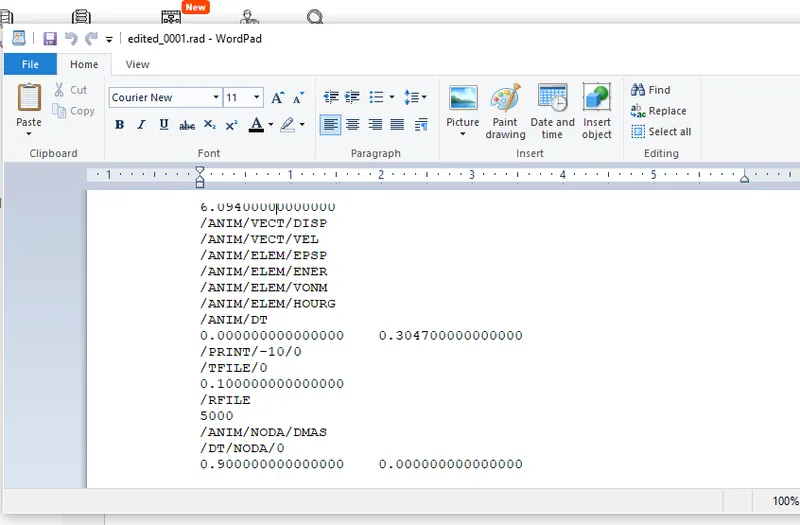 Figure 5
- The 3D meshing of the given models
- Criteria
Tetra element Length=5mm
Tet collapse = 0.15
- Using Volume tetra mesh
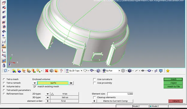
Figure 6
- Set element length to 5 and mesh the volume.Mask a few elements to confirm volume formation
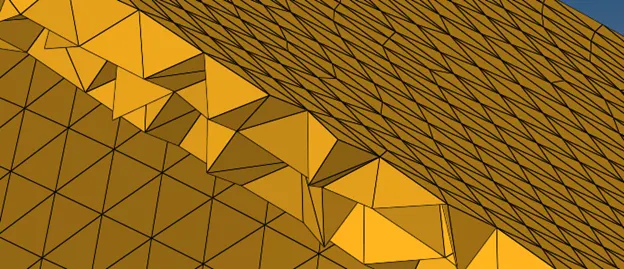
Figure 7
- Check for tet collapse of 0.15 in check elements 3D panel, use tetra remesh if necessary
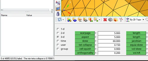
Figure 8
- Similarly, for the second component follow the same procedure.
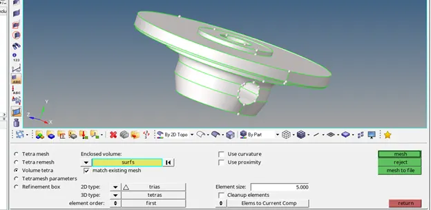
Figure 9
- Mask elements to confirm volume formation
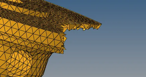
figure 10
- Check for tet collapse of 0.15
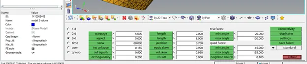
Figure 11
- The final Meshed Model is shown below.
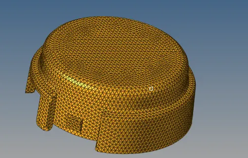
Figure 12
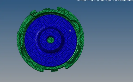
Figure 13
- For Hexa meshing, we start from the base and create a pure quad mesh of size 10mm.
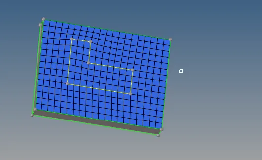
Figure 14
- Using this layer we offset it using elem offset command to create the solid layer
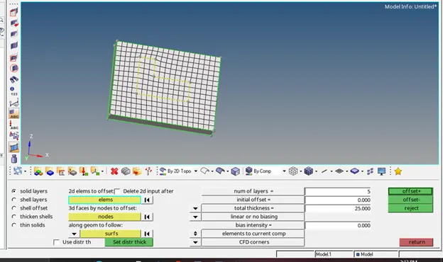
Figure 15 - Now we move to the arm for which we will use the spin command
- Before we do this, we can mask the formed Hexa elements for simplicity using the by config option
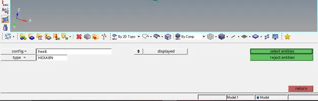
Figure 16
- After this, we need to form a centre for the given curve using the 3node circle centre option.
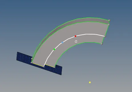
Figure 17
- Select the appropriate elements and point to spin, set angle to 90 and on spin to 25
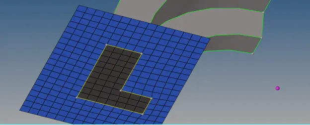
Figure 18
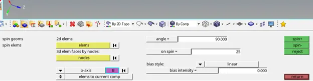
Figure 19
- Use spin- to get the desired result.
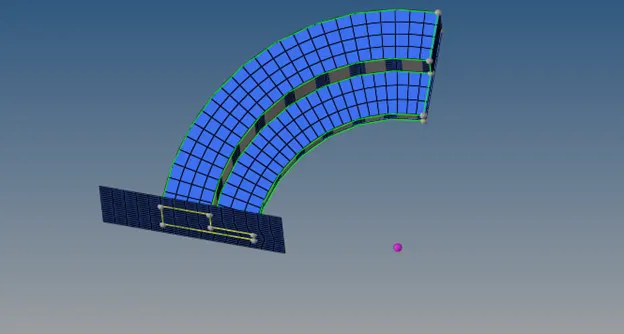
Figure 20
- Now for the next component, we will use linear solid to generate the Hexa mesh
- Before that, using the faces option, we generate 2d elements of the arm component
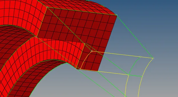
Figure 21
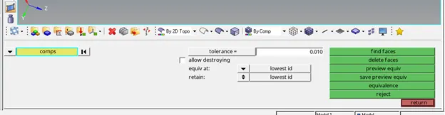
Figure 22
- Then, we mesh the last surface of the component making sure the number of elements is the same as the previous one
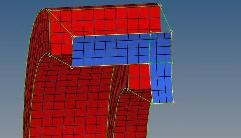
Figure 23
- In 3D linear solid, we now select the elements accordingly.
Note: For alignment, you must select mirror elements
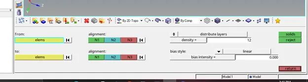
Figure 24
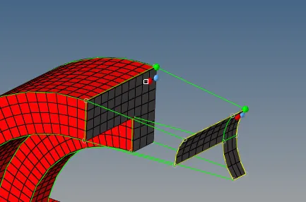
Figure 25
- After meshing we get the hex meshed component.
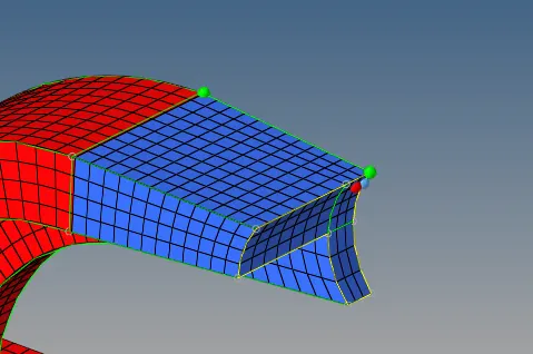
Figure 26
- For the final component, we will use the solid map to generate the 3d mesh.
- First, we generate the 2d mesh on the surface
- Now, we project a node to the bottom surface to further improve mapping accuracy.
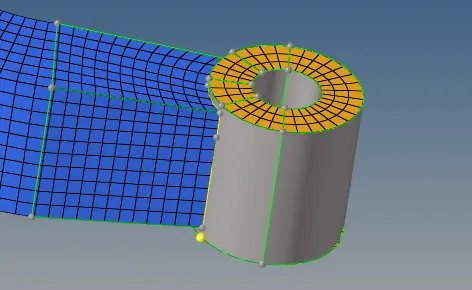
Figure 27
- In solid map, select the dest surf as the bottom face and select the nodes and lines as shown
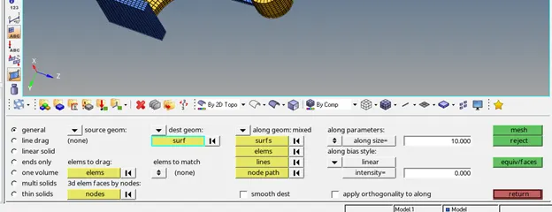
Figure 28
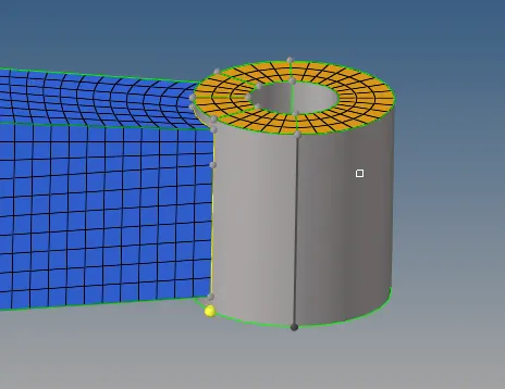
Figure 29
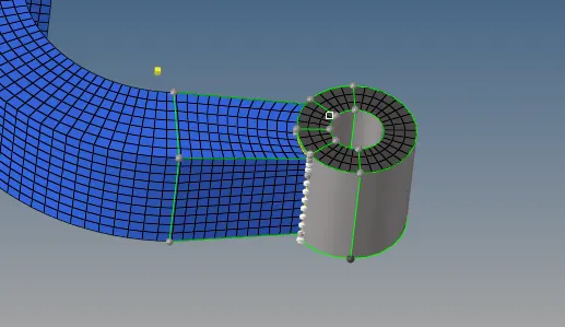
Figure 30
- After mapping, we get the volume mesh in a separate component which needs to be moved using the organize tool appropriately
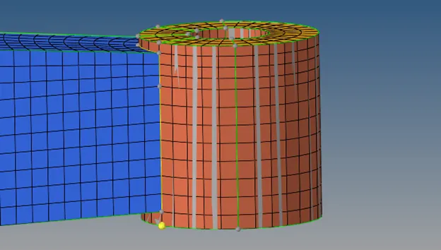
Figure 31
- The final meshed model is shown below
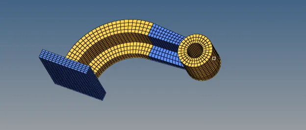
Figure 32
Learning Outcomes
- 3D meshing in hypermesh
- Modifying .rad files
- Timestep
Conclusion
The given models meshed successfully and the .rad files were modified as desired.