RADIOSS Engine File Editing & 3D Meshing
Objective: 1. To find out the time taken by the shock wave to pass through the rail.
2. To create a 1D element and perform 3D tetra and hex mesh on the given components.
Procedure:
Calculation of the time taken by the shock wave to travel through the rail:
1. Import the solver deck instead of geometry and browse the "FIRST_RUN_0000.rad" file and import the file into hypermesh.
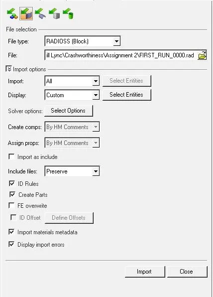
Fig 1: Solver deck import settings.
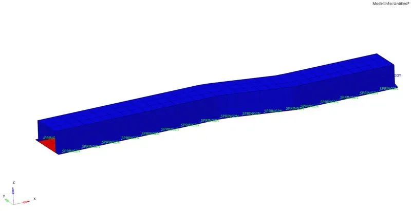
Fig 2: Model as per the starter file with the connectors.
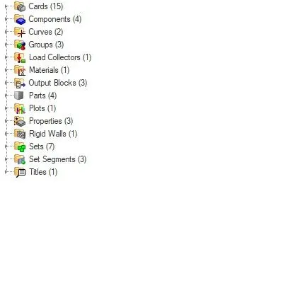
Fig 3: Different items in the model tree.
2. To calculate the speed of sound, we need to know the material properties of the model, mainly Young's modulus and density of the material assigned. To see the value of those, we can check them in the material card data.
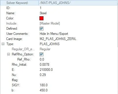
Fig 4: Different property values for the material.
3. From the material card, we can get the values of Young's modulus and density.
Now, to calculate the speed of sound, we can use the formula: c=`root`(E/`rho`)
where c is the speed of the sound
By substituting the values of E and `rho` c=`root`(210000/0.0078)
we get c= 5188.7452166277 m/s.
This is the speed of sound in the steel rail.
The length of the rail is given as 1000mm. To calculate the time taken for the shock wave to pass through the rail completely, we can use the formula: t=l/c.
where t= time in ms; l is the length of the geometry; c is the speed of sound.
`therefore` t=1000/5188.7452166277
t= 0.1927248233 ms
4. Upon calculating these values, the time for termination must be entered in the "ENG_RUN" card.
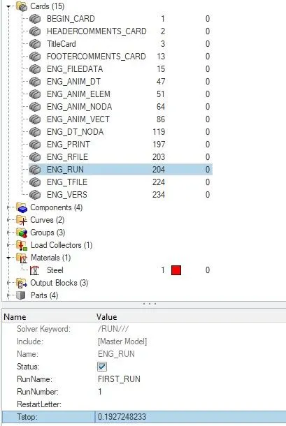
Fig 5: Tstop value is entered.
5. For setting up the animation output, which will result in 20 animation steps, we can divide the time by the required number of animation steps.
`therefore` 0.1927248233/20 = 0.0096362411
This value should be entered in the place of "Tfreq" under the "ENG_ANIM_DT" card.
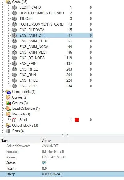
Fig 6: Tfreq value is entered to obtain 20 animation steps.
6. Finally, under the "ENG_PRINT" card, we change the value of "N_print" to -10.
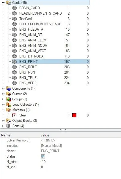
Fig 7: The modified value of N_print.
7. After making the necessary in the card values, it is exported in the form of a solver deck where it generates starter and engine files. To do that, navigate to the export option and select solver deck, and browse the location and name of the file. It generates two files with the same file name with 0000 and 0001.rad.
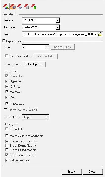
Fig 8: Options for exporting starter and engine files.
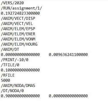
Fig 9: Generated engine file with required settings.
Creation of 1D elements
1. Import the geometry into hypermesh.
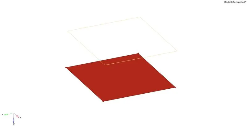
Fig 1: Imported geometry shows two components.
2. Since the top component doesn't have any surface, a ruled surface can be created from the surface options in the geometry tab.
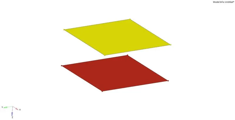
Fig 2: Surface created for the top component.
3. 2D meshing is performed on these two surfaces with two unit element length.
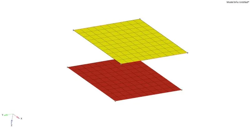
Fig 3: 2D elements created on the two surfaces.
4. These elements are connected with the help of 1D connectors, present in the 1D tab. A rod is associated with the truss as the element. A circular cross-section with a radius of 0.5 units is assigned as a property for the component with P2_Trus as a card image. A bar is associated with the beam element. A box cross-section is set as a property for the component with P2_BEAM as a card image. Two spring elements are created with an appropriate card image in the property.
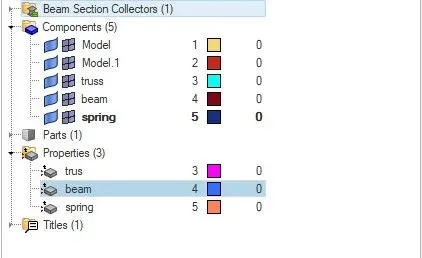
Fig 4: Different components and properties created for each.
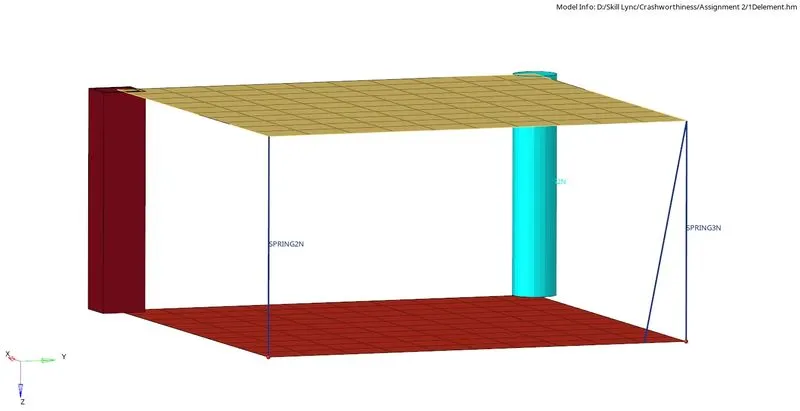
Fig 5: 1D detailed representation of elements.
Tetra meshing of housing component:
1. Import the given housing geometry into hypermesh.
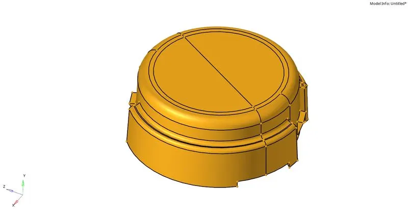
Fig 1: Imported geometry.
2. The model consists of two components, i.e., hub and cover.
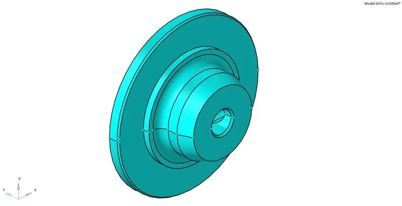
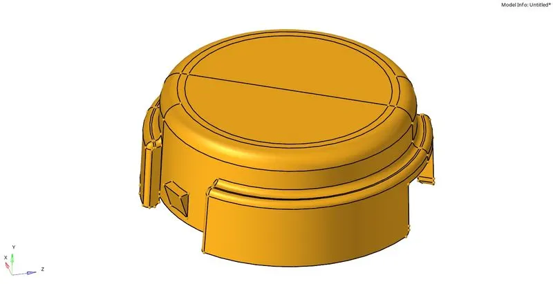
Fig 2: hub and cover.
3. Hide the cover component. Auto mesh with 2D tria elements with a target element size of 5 units.
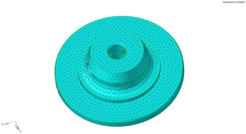
Fig 3: 2D tria mesh generated on the hub component.
4. To generate 3D tetra elements from the 2d tia mesh, navigate to the tetra mesh option in the 3D tab. Select all the 2D elements displayed and generate the 3d mesh.
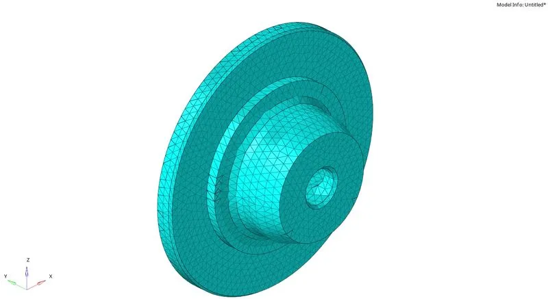
Fig 4: Tetra mesh generated from the 2D tria elements.
5. Hide the hub component and unhide the cover component. Volume mesh from the 3D tab is performed on this component.
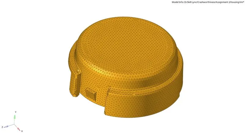
Fig 5: Tetra mesh generated on the cover component.
Hex meshing of arm bracket:
1. Import the given geometry into hypermesh.
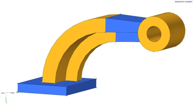
Fig 1: Imported arm bracket.
2. The arm bracket consists of four different components, i.e., base, arm, extension, and the boss. Each of these is separated meshed with 2D elements first on the surfaces. Keeping the element length as ten units and type as quads only. The generated 2D elements are then dragged/spun across the length of the components. Using linear solid and solid map options from the 3D tab, 3d elements can be created from 2D quad elements


Fig 2: Solid map and linear solid options for creating 3D elements from 2D.
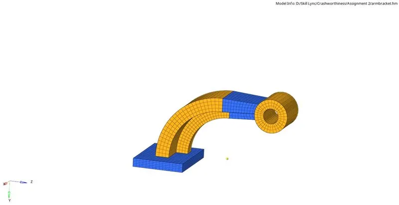
Fig 3: 3D quad element mesh is created on the arm bracket.
Conclusion: 1. Time taken by the shock wave to pass through the rail was calculated and modified in the engine file.
2. Created 1D elements and performed 3D tetra and hex mesh on the given components.