Assignment 2-RADIOSS Engine File Editing & 3D Meshing Challenge
QUESTIONS:
1. Check the material properties of the rail component and calculate the speed of sound in steel rail?
SOLn:
- So after opening the FIRST_RUN_0000.rad we will get material properties of steel rail.

Where
ρ=0.0078gm/mm³
E=210000MPa- So now SPEED OD SOUND (C)= (E/ρ)½
= (210000/0.0078)½
C= 5188.75 m/s
2. The length of the rail is about 1000 mm.calculate the time takes for a shock wave to travel from one end of the rail to the other.
Soln
- Shock wave speed= speed of sound = 5188.75 m/s
- now time(t)= Distance(D)/Speed of shockwave
=1/5188.75
t=0.1927 ms (mili second)
3. Time for sound to travel length of rail is 0.1927 ms
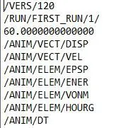
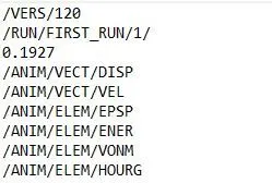
4.Edit the engine file so that the stress wave can be monitored, moving from one end of the rail to the other during impact -this will require a termination time equal to the time it takes for the sound to travel the length of the rail(set on/RUN card)
Soln:
- So the edited format is shown below:
First open the 0001.rad file in notepad and proceed the further steps as shown:
Before:
After
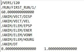
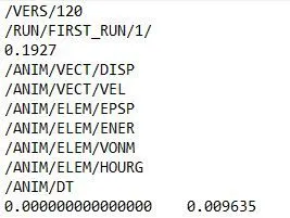
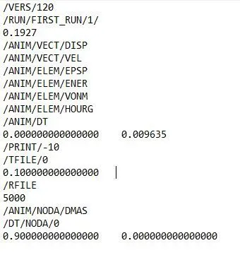
5.Set the frequency of animation output to a time that will give 20 animation steps(/ANIM/DT)
Soln:
- So the Frequency (f)=time/no. of revolution
=0.1927/20
f=0.009365 ms - For this go to he STEPS>/ANIM/DT option and change the frequency as shown:
Before:
After
6.Change /print -10.
Soln:
- The value is shown below:
7. 3d meshing tetra mesh and hex mesh
- Repeat class examples and, maintain the quality.
- Target tet size=5mm,hex size=10mm,tet collapse=0.15.
A. 1D Element
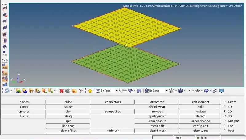
- First import .STEP file in Radioss and after that perform meshing operation on it.
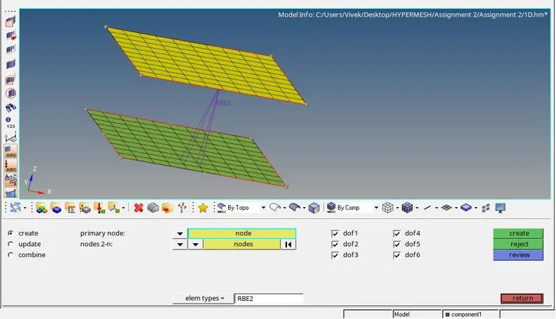
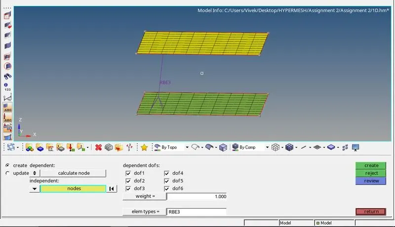
- Since it is a 1D element we have to connect with RBE2 or RBE3 connection.
- For meshing 2D>AUTOMESH and select the surface and click on mesh as shown:
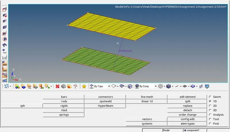
- Now to create a connection between this two surfaces go to 1D>rbe3/rigids/spring according to requirenmnet as shown below:
- Different connections have different properties.
RBE2 and RBE3 Connection
- There are two types of elements used to represent a rigid connection viz. RBE2 and RBE3 elements. The property of connection with the RBE2 element is that there is a single master node (or independent node) and multiple slave nodes (or dependent nodes).
- It means when multiple nodes are selected as slave nodes, and given one master node, the master would be the center of mass/load of all the slave nodes.
- However, using RBE3 elements, there can be multiple master nodes and a single slave node, which means whatever load that is coming on the slave node would be distributed among all the master nodes.
SPRING
- The spring can be two-noded or three-noded. In this model, the two noded spring is created using 1D > springs
B. ARM BRACKET
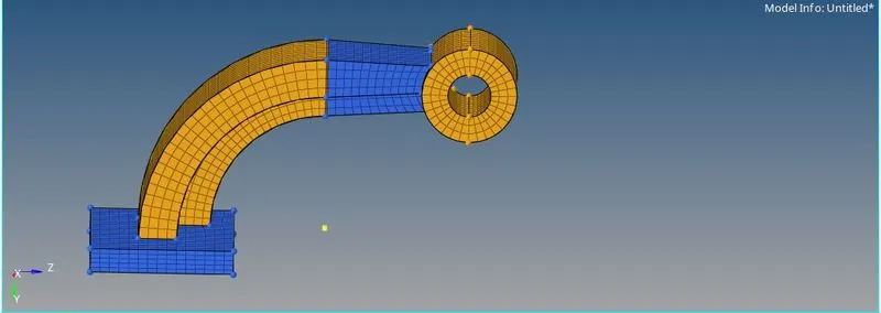
- Now for arm bracket we will peform the 3D meshing or volume meshing. In the given image the arm bracket is divided into four parts so we will perform one by one 3D meshing on each part.
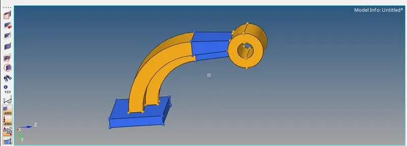
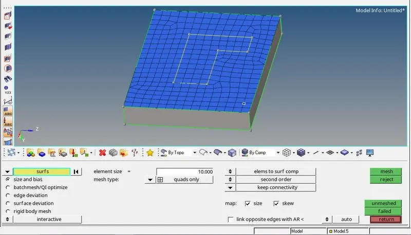
- So now first we will perform meshing on the model 1 for that perform the 2D mesh on the surface of the component and then offset that mesh as shown below:
- To perform 2D mesh go to 2D>AUTOMESH. We will perform quads only mesh here.
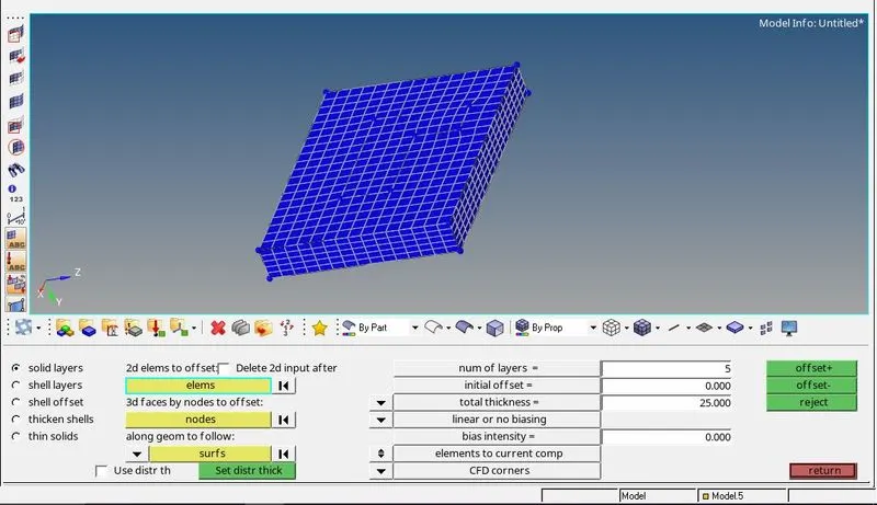
- Now after that we can to create 3D mesh for that go to the 3D>elems Offset.
- Then select the 2D mesh and as an element to offset after that select the surface for along geometry to off set give the total number of layers and total thickness after that click on offset as shown:
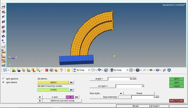
- Now next is part 2 fo that we will use anothe method know as spin.
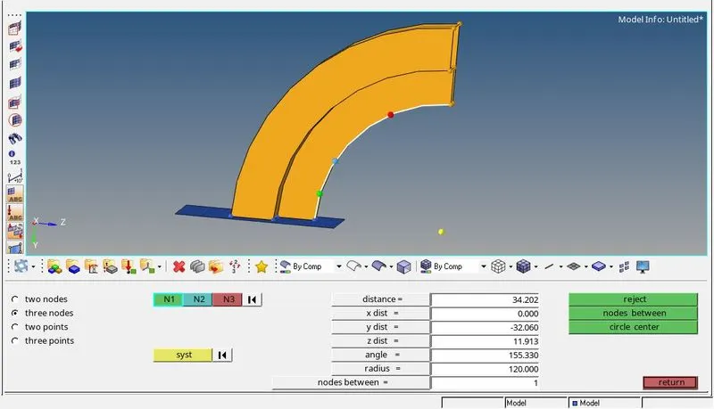
- For that go to the 3D>SPIN>SPIN ELEMS after that create a centre of the curve using the 3 nodes.
- Then select the center of the curve and click on offset as shown:
Creating Center of th Curve
Creating 3D mesh using spin
- Now for model 3 it is a tappered shape so we will use 3D>linear solid.
- We should mesh each end by 2d element and join the same in this method
- Already one end of arm stright component is meshed by hexa element , to extract 2d element from hexa element, go to TOOLS>FACES extract faces option
- One end of the component will have 2d elements, mesh the other end with same number of elements to avoid penta elements.
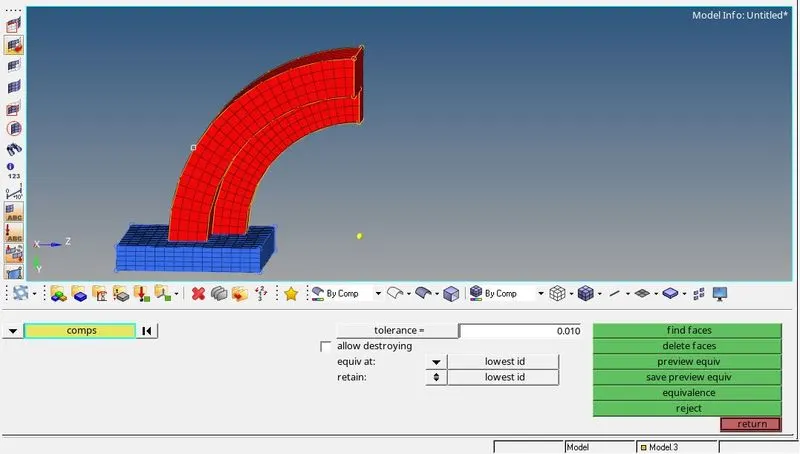
- Creating 2D mesh of end on the coponent:
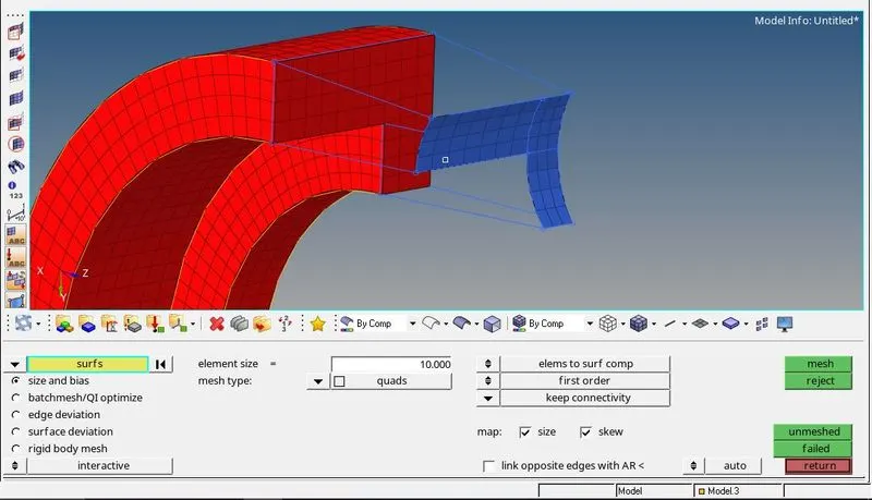
- After that 3D>linear solid.
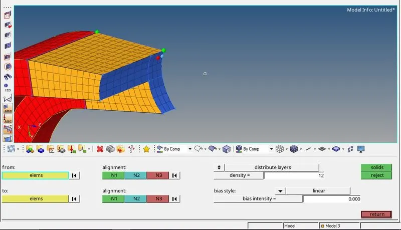
- After that delete the face which we created using Tools>Faces>Delete
- Now for the model 4 we will use 3D>solid map.> GENERAL
- In this we have to select the SOURCE GEO, DESTINATION GEO, ALONG GEOM amd then perform the 3D meshing as shown:
- Initially, one side surface has meshed with 2D quad elements .
- The same number of nodes should be there at both ends. In order to have the quad elements.
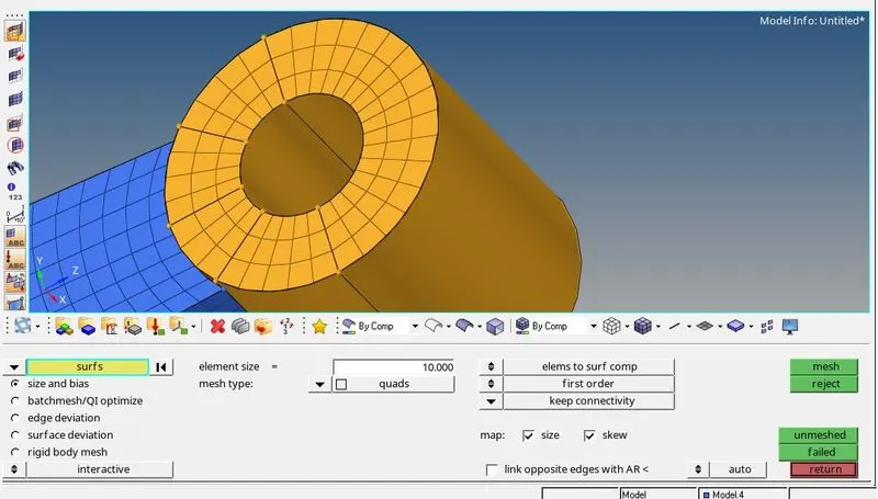
- So the final component will look like this:
C. HOUSING
- So for performing the 3D meshing on this component
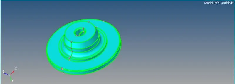
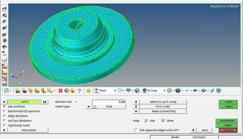
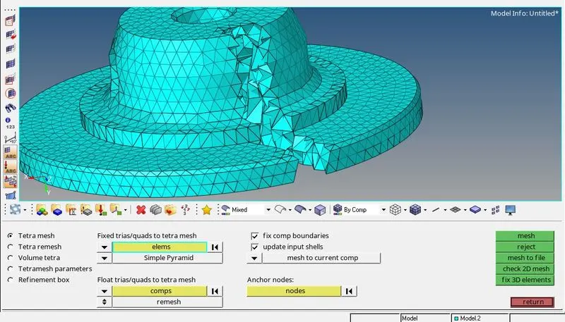
- First we will perform 2D meshing on the component and after that we will peform 3D>tetramesh
- So the component will look like as shown:
- 2D>automesh:
- 3D>tetramesh:
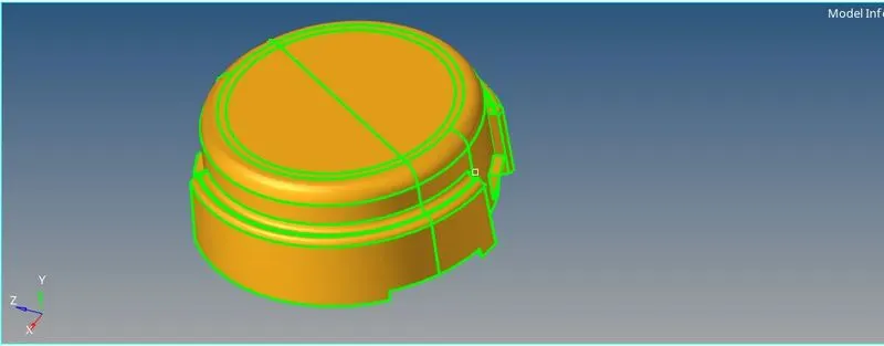
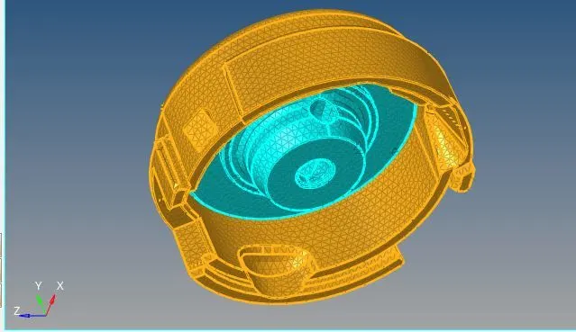
- For the second componnet we will use direct Volume meshing process.
- For that go to VIEW>BROWSER>HYPERMESH>UTILITY in that Select GEOM/MESH after that go to quick tetramesh and perfrom the operation as shown:
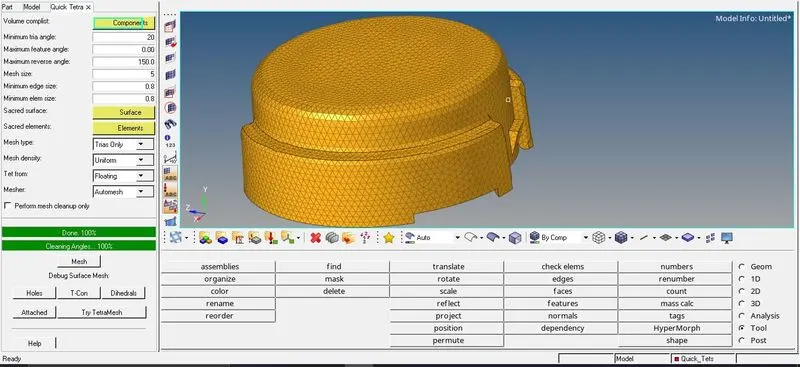
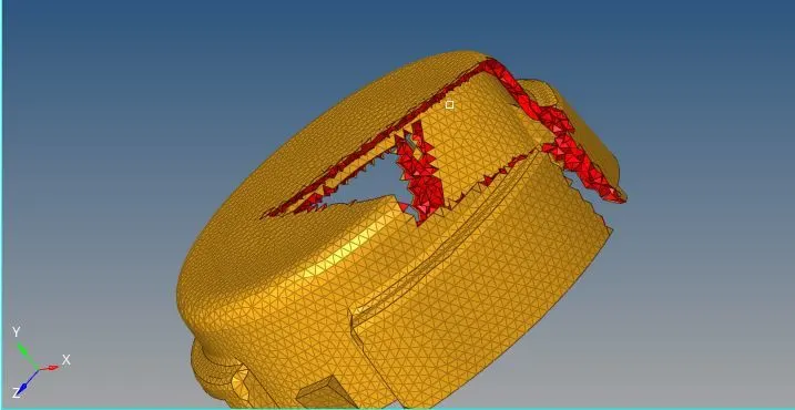
- Actual component will look like this:
CONCLUSION:
- Understood how to calculate speed of sound in different material, frequency, time step
- Understood how to read input radioss file
- Understood how import the radioss solver deck file anf feed the value
- Understood how to export the file in .rad format
- Got to know how to create 3d tetra mesh and hexa mesh
- Learnt how to give diffrent type of 1D connection and hyperbeam concept