Assignment 2-RADIOSS Engine File Editing & 3D Meshing Challenge
ASSIGNMENT 2 - RADIOSS ENGINE FILE EDITING & 3D MESHING
AIM:
- To calculate the speed of sound in steel rail according to the material properties.
- To calculate the time to travel accross the length of rail of1000mm.
- Editing the engine file to monitor the stress wave
- Set the frequency of animation output to a time that will give 20 animation steps.
- Change /print -10 from radioss engine file.
- Also 3D mesh the given components according to the criteria.
For 2D mesh
| Parameter | Value |
| Target element size | 5 |
| Min element size | 3.5 |
| Max element size | 7 |
| Aspect ratio | 5 |
| Warpage | 15 |
| Skewness | 60 |
| Jacobian | 0.5 |
| Min tria angle | 20 |
| Max tria angle | 120 |
| Min quad angle | 40 |
| Max quad angle | 140 |
For 3D mesh
| Parameter | Value |
| Target tetra element size | 5 |
| Target hexa element size | 10 |
| Tet collapse | 0.15 |
PROCEDURE:
A] RADIOSS ENGINE EDITING
- Open the given engine file ending with 0000.rad with some text editor.
- Check the units of the file.
-
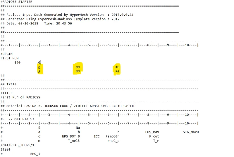
- To calculate speed of sound travelling in the rail we know the formula is
c= `sqrt(E/rho)`
- We get the values of E and `rho` from the engine file.
-
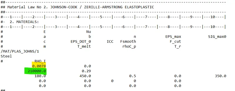
- Here E=21000 N/sq.mm or MPa and density `rho`= 0.0078 g/sq.mm
- So c=`C=sqrt(210000/0.0078)`
c= 5188.745217 mm/ms
- Time required to travel through the 1000mm rail is given by the formula
`Delta T=l/c`
- So `Delta T= 1000/5188.74521663`
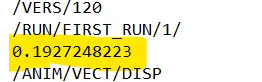
`Delta T=`0.1927248223 ms
- Changing the value of time in radioss engine as shown below
- We also need to change the value of frequency for 20 steps of 0.192 ms.
- Frequency is calculated by the formula
`f=T/n`
`f=0.1927248223/20`
f=0.00963641117
- To change the value of frequency in radioss engine we do as shown below
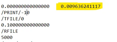
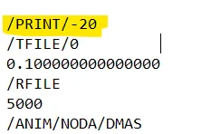
- We also need to change the /PRINT/-10 which we do as shown below.
B] 3D Meshing
1) Housing model.
- We import the geometry from the given stp file.
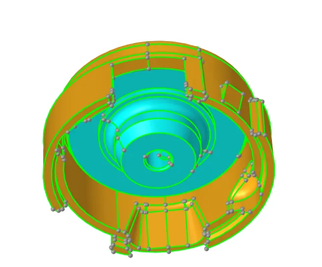
- Then we proceed to do the 2D meshing using Automesh panel. We do the meshing on individual component so we hide the other component.
- We give the target element size of 5 and select trias for meshing process and mesh the components.
- We check the criteria using element checkup panel from the tools section.
- If the trias are failing the criteria we remesh them using element cleanup panel from 2D section.
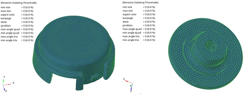
- After cleaning up the 2D mesh we do the 3D meshing.
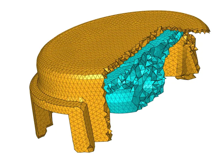
- We use the tetramesh panel to create a tetramesh using 2D elements. We edit the tetramesh parameters of tet collapse to 0.15 and define the minimum tet element size of 3.5.
- We select the 2D mesh to create tetramesh.
- We do element checkup of tetramesh created using 3d section of element cleanup panel to see the minimum tetcollapse value. If elements are failing we do remesh using the tetra remesh option from the tetramesh panel.
- A 3D mesh is created.
2] Arm bracket model.
- We import the given stp file.
- We create a 2D quad mesh on the base surface of model.
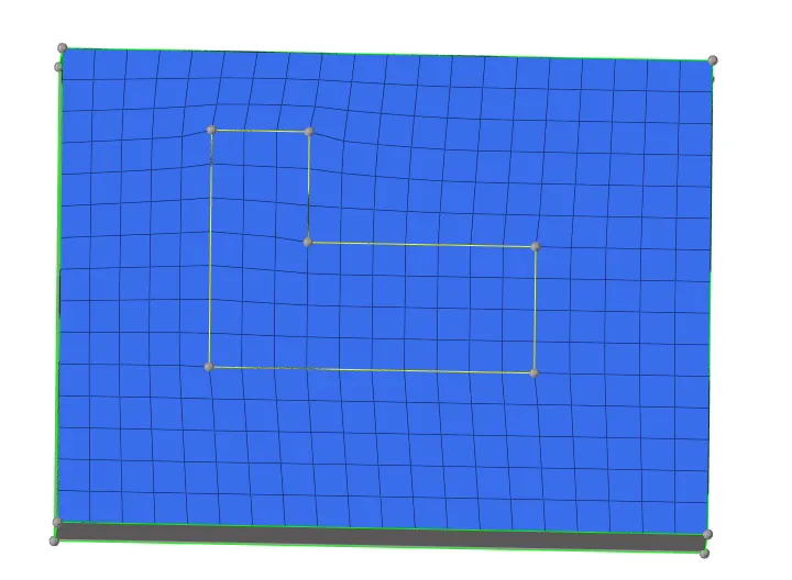
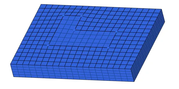
- We then use the element offset panel from 3d section to create hexa mesh of the base component.
- We select the 2d elements and the surfaces and create 5 layers for thickness of 25 as the component's thickness is 25.
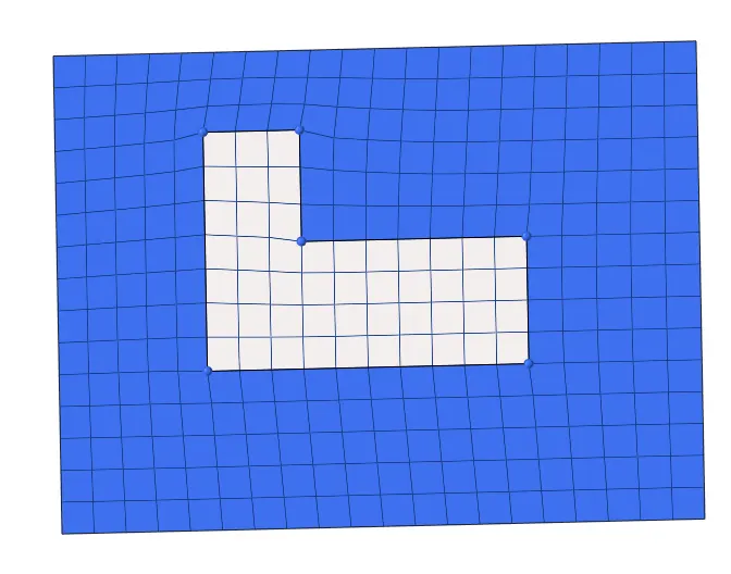
- Then for the constant L section curve we use the spin panel to create a 3D mesh. We first create a temporary centre node for the curve section. Then we select the elements as shown below to spin 90 degrees for arc length of 25.
- 3D elements are created for the constant L section curve.
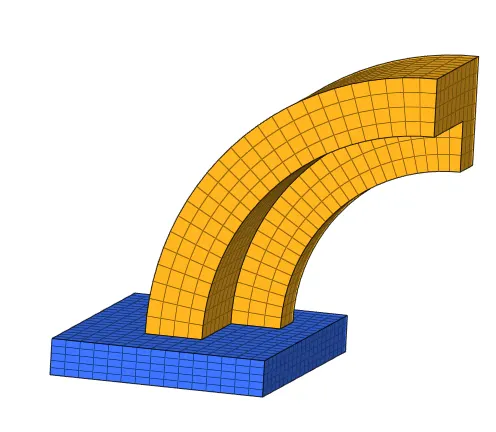
- For the tapered L section, we first create faces for the constant L section curve and also mesh the other end of the tapered L section.
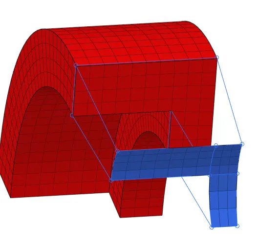
- We check the number of elements are on both faces are equal or not.
- Then we proceed to create 3D elements using linear solid panel. We select the face elements and give appropriate allignment to create a 3D mesh.
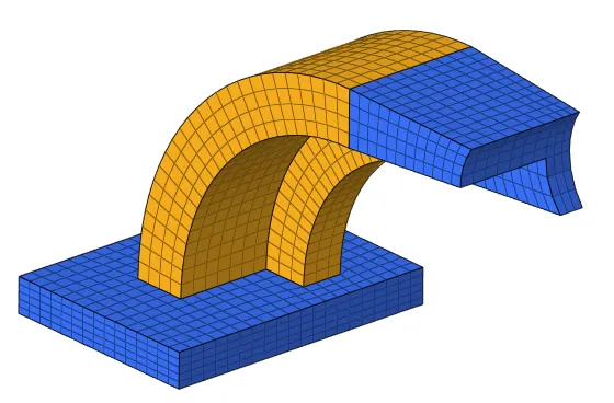
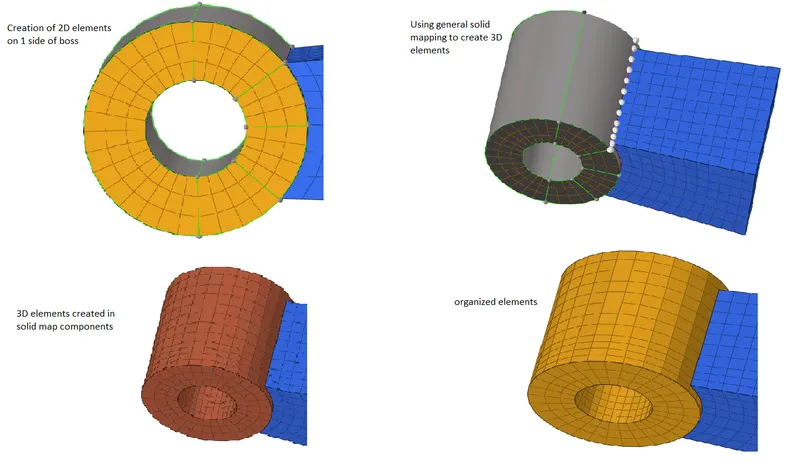
- For the boss section of the model we create a 2D mesh on 1 side of the boss and then use general solid mapping to create a 3D mesh.The 3D mesh is created in a new component called solid map. So we use organize panel to move those 3D elements to the boss component.
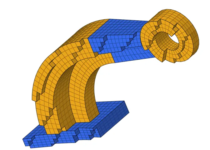
- We delete all the 2D elements which were required to create hex elements.
- We have created a 3D mesh for the given arm bracket model.
CONCLUSION:
- From this assignment I learned the radioss engine files and the notations inside the file.
- Also learned how to calculate speed of sound and time.
- I learnt how to create 3D mesh using tetramesh panel, linear drag, spin, solid map and elem offset panel.