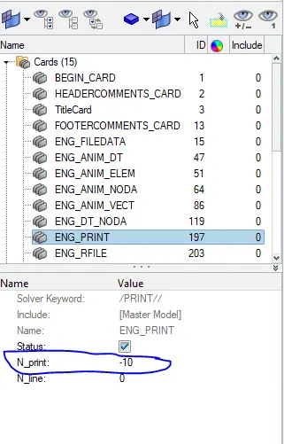
Assignment 2-RADIOSS Engine File Editing & 3D Meshing Challenge
AIM :- Mesh the given two components ( hub, cover) using 3D TETRA elements and mesh the arm bracket using 3D HEXA elements.
quality criteria for 2D mesh
max. length = 7mm
min. length = 3.5mm
aspect = 5
skew = 60
jacobian = 0.5
warpage = 15
min tria angle = 20
max tria angle = 120
min quard angle = 40
max quard angle = 140
quality criteria for 3D mesh
target TET size =5mm
target HEX size = 10mm
tet collapse = 0.15
PROCEDURE :-
- Import the given .hm files into hypermesh , go to import - import model - browse .hm files - click on import.
HUB :-
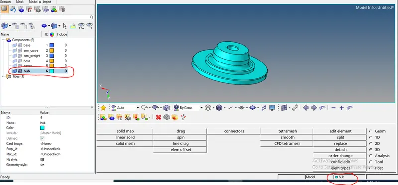
- put required component as current component ,
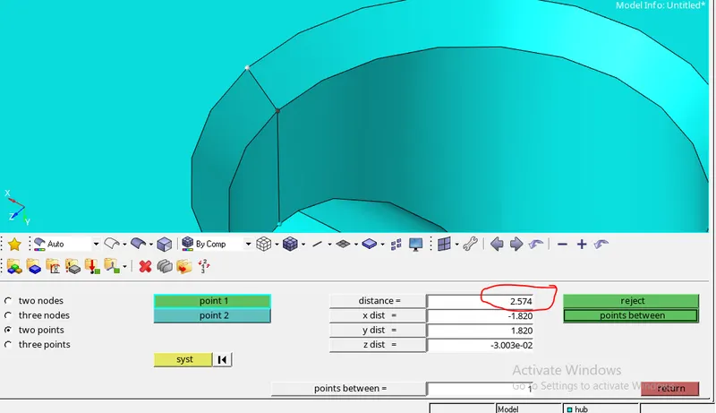
- We are taking 3.5mm as mnimum length of an element, so supress the edges which are having distance less than 3.5mm
-
- to supress/defeature the edge , go to geom- quick edit - toggle edge.
- all these steps are comes under geometry cleanup stage , after succesfully completing geometry cleanup stage go for 3D meshing.
- there are 2 types of 3d meshing methods one is convert 2d mesh to 3d mesh and another one is direct 3d mesh.
- in first type , we create 2D shell elements on top of geometry then check for quality of mesh. after clearing quality criteria convert 2D mesh into 3D mesh.
- it requires more time and energy of engineers but we can get better quality mesh, which leads to good and accurate results.
- in seconed type , we do 3D mesh directly on object using tetra or hexa elements.
- it requires less time and energy of engineers compare to first method but we don't have proper control on mesh over quality, which leads to bad and inaccurate results.
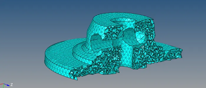
for this HUB component we are using first method ( convert 2d mesh to 3d mesh)
- first create a 2d shell elements on top of geometry , go to 2D- automesh - give parameters - click on mesh
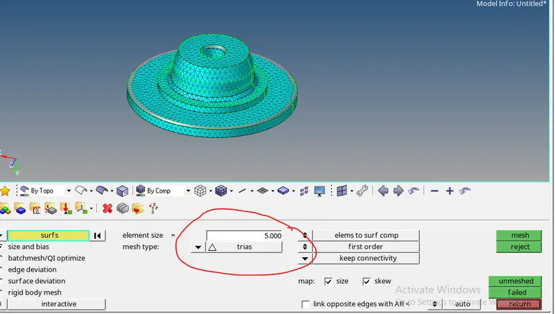
- after meshing go for quality check
- first give parameters for quality check , go to - preferences - criteria file settings.
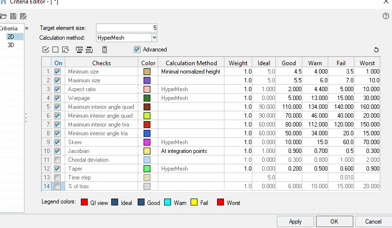
- go to - 2d - quality index
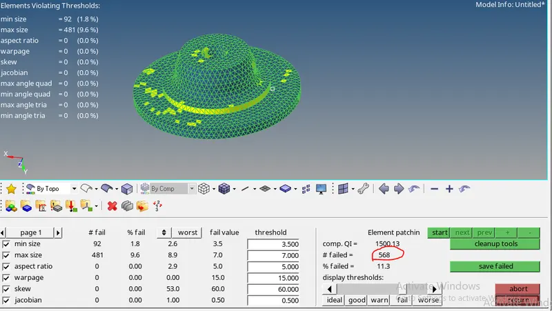
- initially 568 elements failing for quality , so clear these failing elements and bring 568 to 0 using cleanup tools , element edit tools .
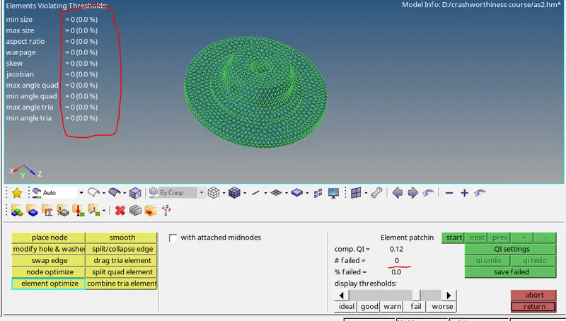
- from the above pic we can see that , all elements were cleared quality criteria . so now convert this 2d mesh into 3d mesh.
- for 3d meshing , go to - 3d - tetra mesh .
- before 3d meshing set tetramesh parameters.
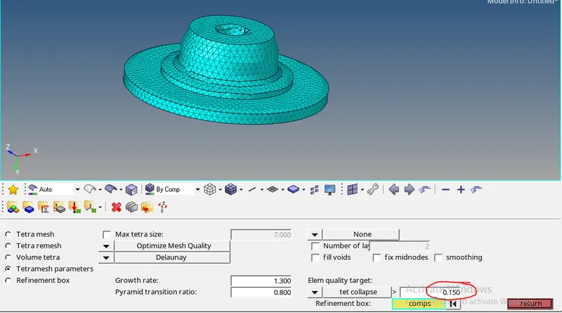
- go to tetra mesh - select elements - click on mesh
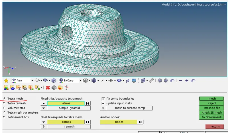
- after creating 3d tetra mesh go for 3d quality check mainly tet collapse
- go to - tools- check elements -3d - tet collapse
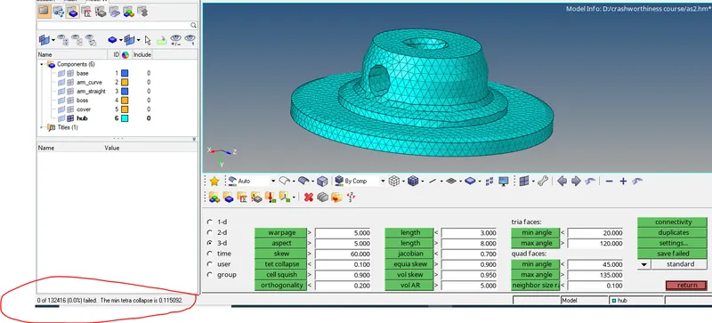
- from the above pic we can see that , all elements were cleared quality criteria.
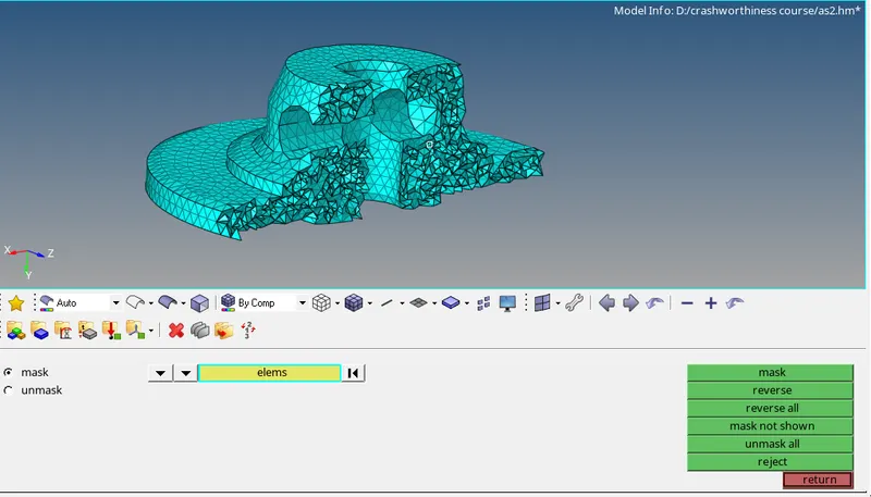
- to check whether 3d mesh created properly or not use mask (f5) option.
COVER:-
- follow the above mentioned procedure for geometry cleanup
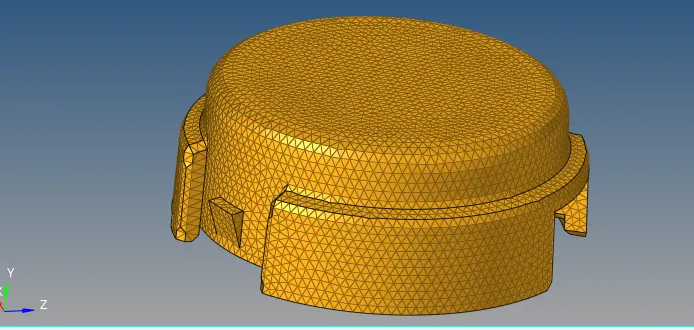
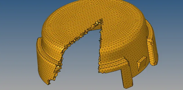
- for this component, create 3d tetra mesh directly on object using volume tetra option.
- go to - 3D - tetra mesh- volume tetra.
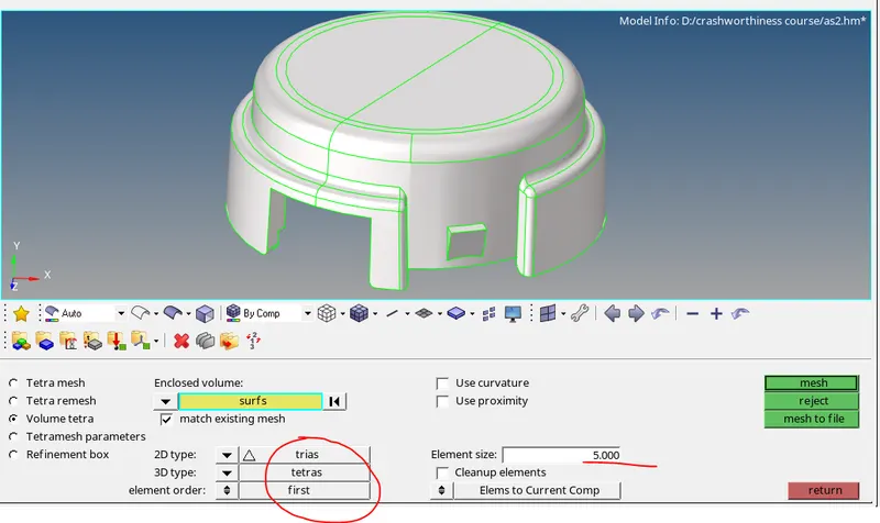
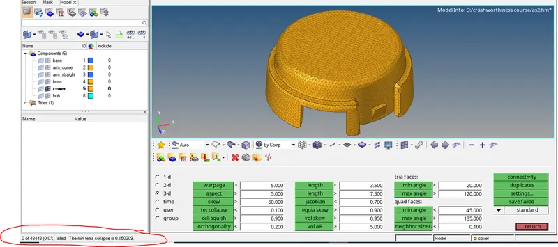
- after creating 3d tetra mesh go for 3d quality check mainly tet collapse
- go to - tools- check elements -3d - tet collapse
ARM BRACKET :-
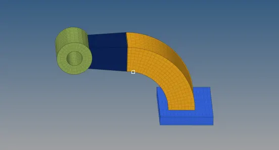
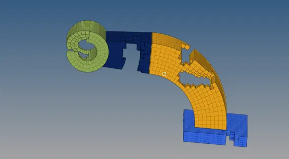
- for this model , create 3d HEXA mesh directly on object.
- there are 4 components in this model ( base , arm_curve , arm_straight , boss) , mesh each component seperatly.
base
- create a 2d mesh on top surface , go to - 2d- automesh
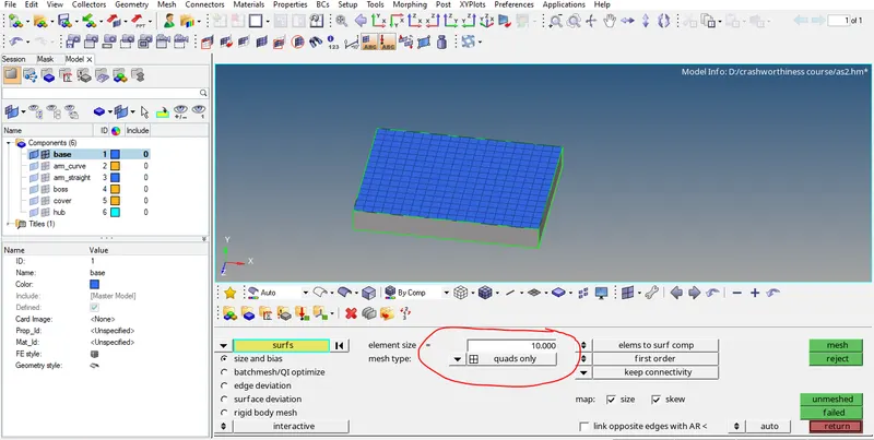
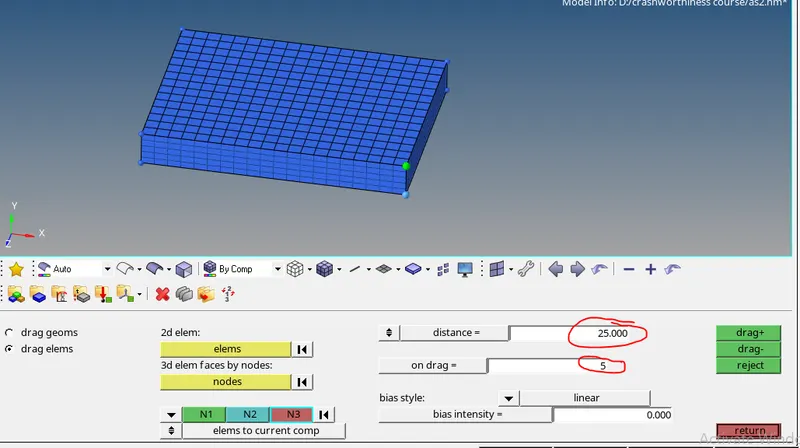
- create a 3d mesh using this 2d shell elements
- go to - 3d- drag - drag elements.
arm_curve
- it is a curved part so we use spin option to create 3d elements.
- we need a center pont to spin the elements , press f4 to create circle centre point.
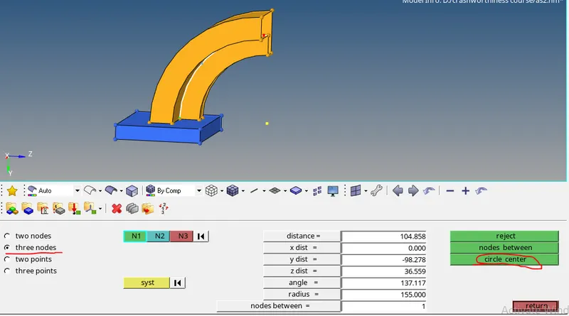
- go to - 3d- spin - spin elements
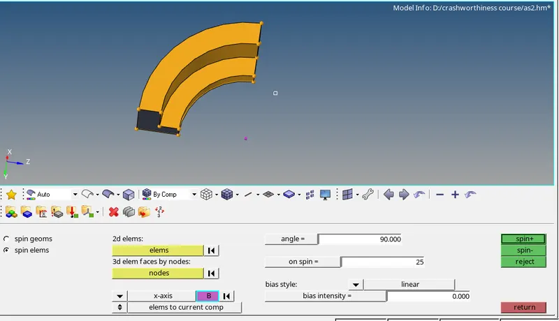
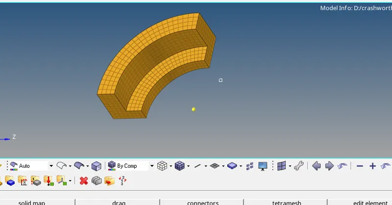
arm_straight
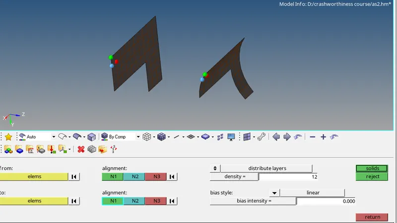
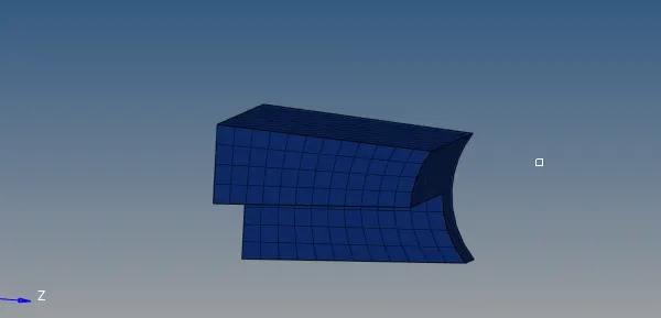
- it is a uniform crooss section component with some deviation in shape , so linear solid option is best suitable to create 3d mesh for this kind of components.
- to create solid between two elements using linear solid , elements from source is exactly equal to elements in destnation.
- for alignment, select N1N2N3 for both at same location
boss
- it is a cylindrical shape component , so simply we can create 2d mesh on one side and drag these elements to other side to create 3d hexa elements. but this is not a recommanded method bcz it lost connectivity with adjacent arm_straight component.
- by using solid map option we can create hexa mesh with proper connectivity.
- create a 2d mesh on one side , go to - 2d- automesh
- go to -3D- solidmap
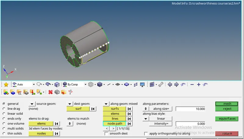
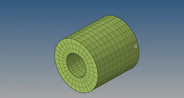
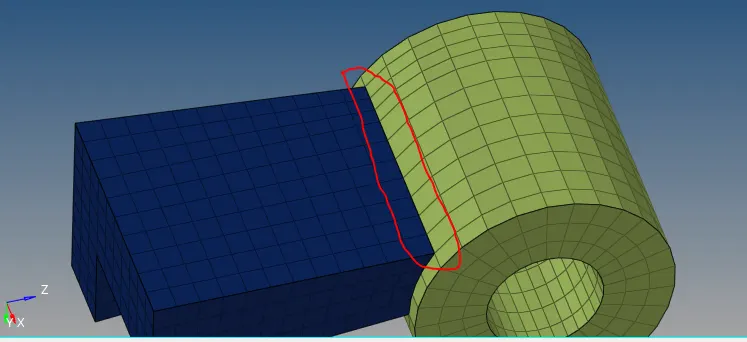
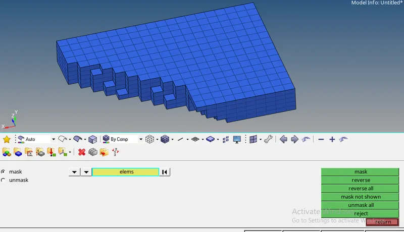
- after created a 3d mesh delete the previous 2d shell elements
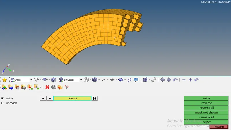
- for that first hide 3d elements using mask option.
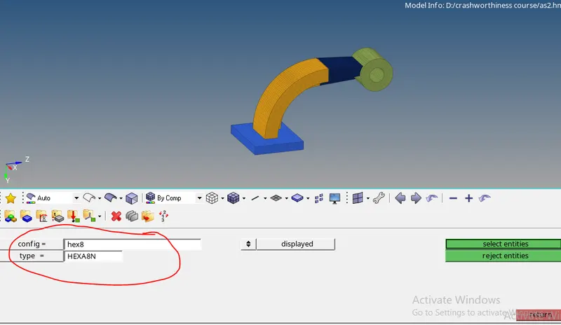
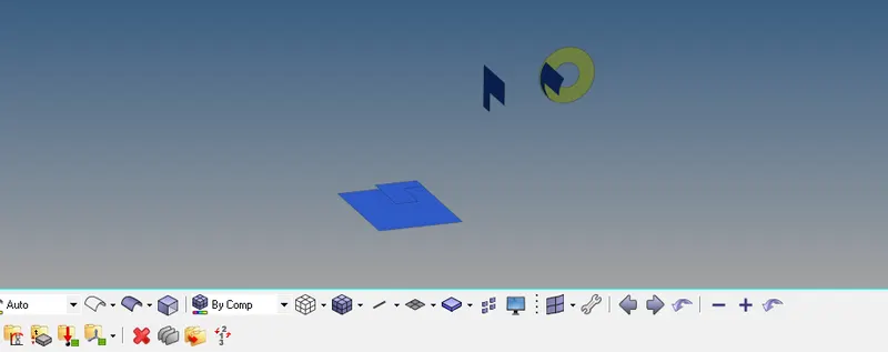
- delete the remaining 2d shell elements
RESULT
- Created a 3D mesh ( tetra & hexa) on given components in two methods , with given quality criteria.
1. hub
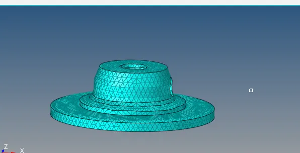
2. cover
3. arm bracket
Answers
1. speed of sound (C) = √ E/ρ
where
E = youngs modulus
ρ = density
given data
E=210000
ρ= 0.0078 g/mm^3
= 0.0078 * 10^6 = 7800 kg/m^3
substitute E & ρ values in formula
= √210000/7800
= √26.92
= 5.188
speed of sound (C) = 5.1887
3. Time for sound to travel = L/C
where
L= critical element length
C= speed of sound
given data
L = 1000 mm
C = 5.1887
substitute L & C values in formula
= 1000/5.1887
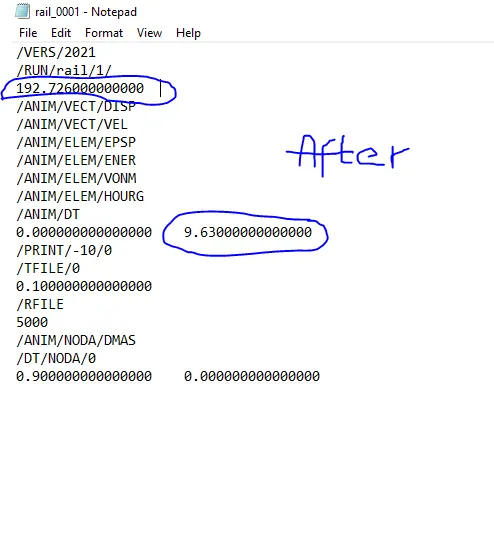
= 192.726
Time for sound to travel = 192.726
5. freequency = time for sound to travel/animation steps
= 192.726 / 20
= 9.63
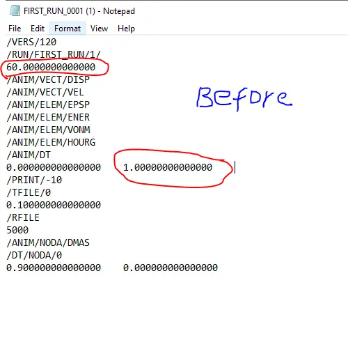
engine file edit
6.