Assignment 2-RADIOSS Engine File Editing & 3D Meshing Challenge
ASSIGNMENT 2: RADIOSS ENGINE FILE EDITING AND 3D MESHING
OBJECTIVE:
- To determine and edit the input values for the given Engine file and observe the stress wave propagation.
- To conduct 3D meshing using tetra mesh and hexa mesh for the given models.
Radioss Engine file editing
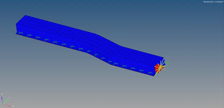
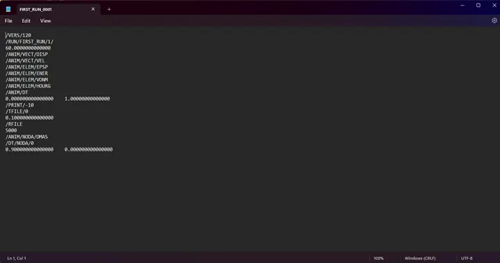
Model and its Engine file
CALCULATIONS:
- Check the unit system followed by the starter file.
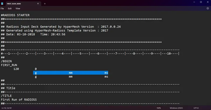
- Check the values for Young's modulus (E) and Density (`rho`)for the material (Steel) assigned.
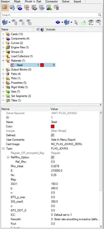
- Given, E=210000 and `rho`=0.0078
- Speed of sound, c=`sqrt (E/rho)`
c=`sqrt (210000/0.0078)`= 5188.745mm/ms
- If length of the rail is 1000mm, then the time taken for a shock wave to travel along its length is
t=l/c=1000/5188.745= 0.19272ms
- Time for sound to travel length of rail, t=l/c=1001.25/5188.745
RUN time, t(stop)=0.19296ms
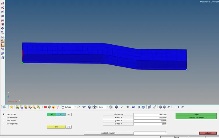
- Frequency of animation output for 20 steps, DT=t(total)/20
T(freq)=0.009648ms
PROCEDURE:
- Open the FIRST_RUN_0001 (Engine file).
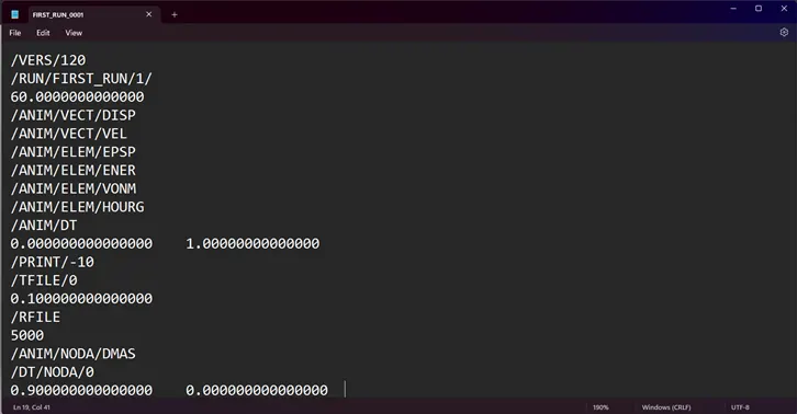
- Edit the text and change values for /RUN/FIRST_RUN and /ANIM/DT.
- Change /PRINT/-10 to /PRINT/-20.
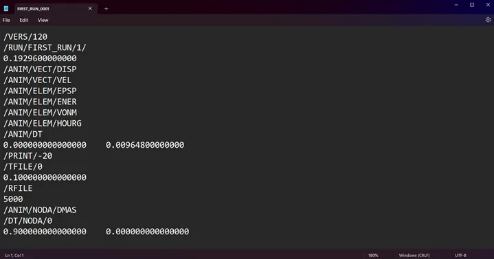
- Save the engine file.
- Import the starter file to Radioss under Analysis panel and check the results.
RESULT:
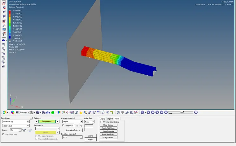
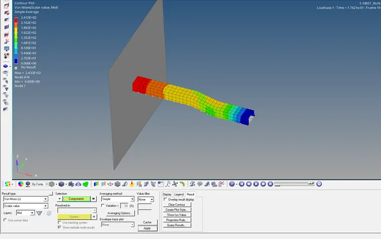
- The animation result is viewed in HyperView window.
- Apply the Contour plot using Von Mises stress variation.
- A single stress wave can be observed moving from one end of the rail to other end under 20 frames.
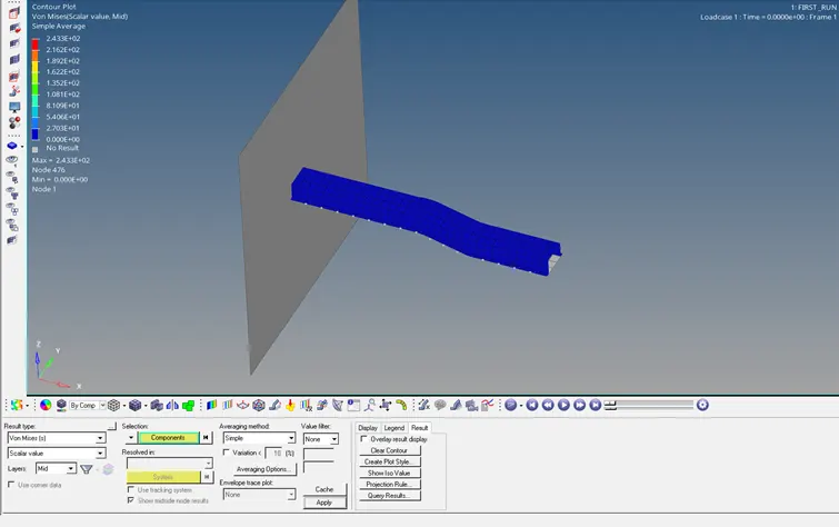
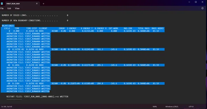
- /PRINT/-20 input in engine file generates energy error and mass data at an interval cycle of 20.
Tetra Meshing
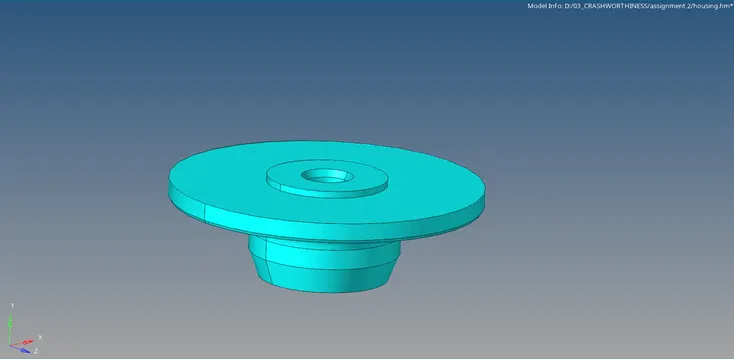
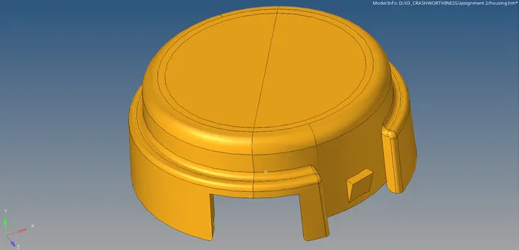
Housing CAD model for Tetra meshing
PROCEDURE:
- Open the model and view in By Topo mode. Check the surfaces for geometric errors or edge connectivity.
- Set the mesh parameters in the Mesh settings.
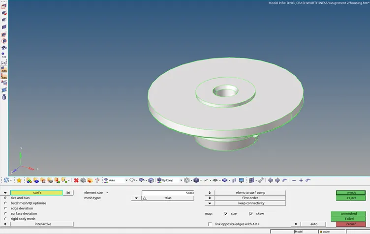
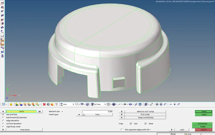
- Mesh(Trias) the entire surfaces maintaining the quality criteria and complete the model by 2D meshing.
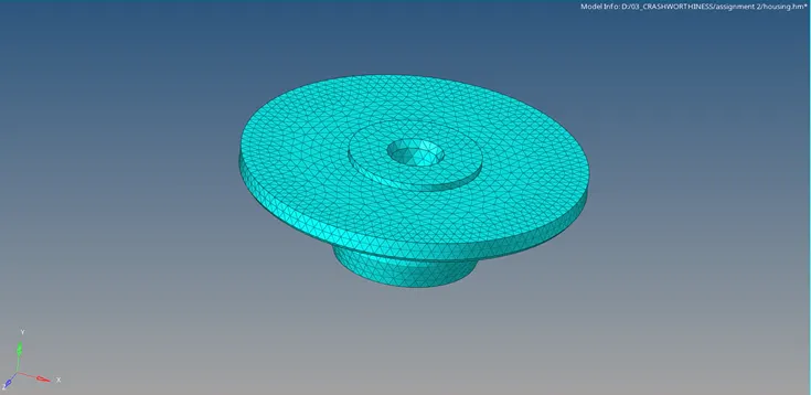
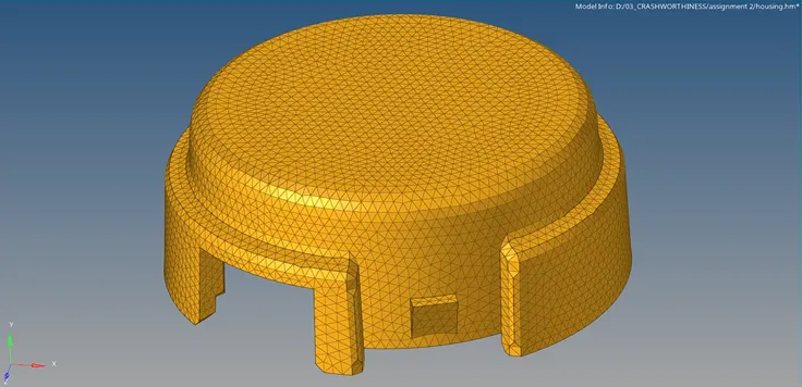
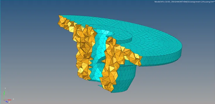
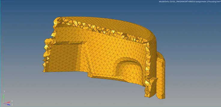
- In 3D menu, select Tetramesh option to convert the 2D elements to 3D Tetra mesh.


- Delete the 2D elements.
Final Model:
RESULT:
- The given models have been 3D meshed using tetra elements.
- The tet collapse is checked and cleared.
HEXA MESHING
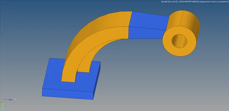
Arm bracket CAD model for Hexa meshing
PROCEDURE:
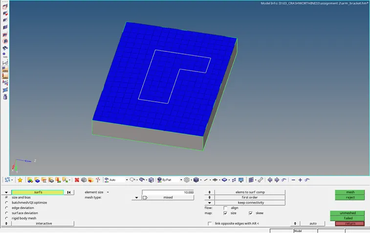
- Select the base for surface meshing maintaining quad elements.
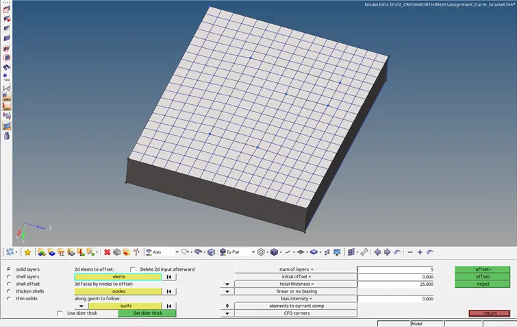
- Create 3D elements from the shell mesh by Elems offset panel.
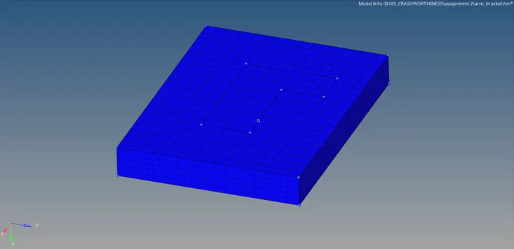
- Find the arm curve centre using three nodes option.
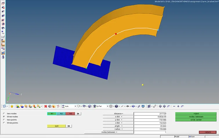
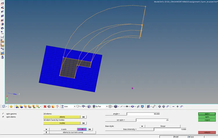
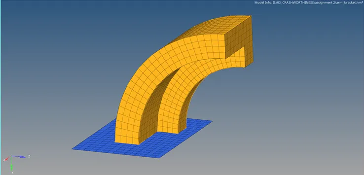
- Select and spin the required 2D elements from the base at 90 degrees.
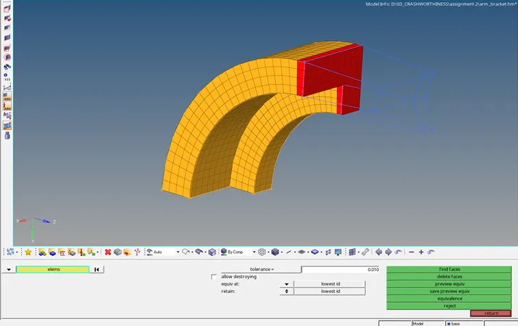
- Create 2D elements for the arm straight component using Faces panel.
- Mesh the opposite surface with matching nodes.
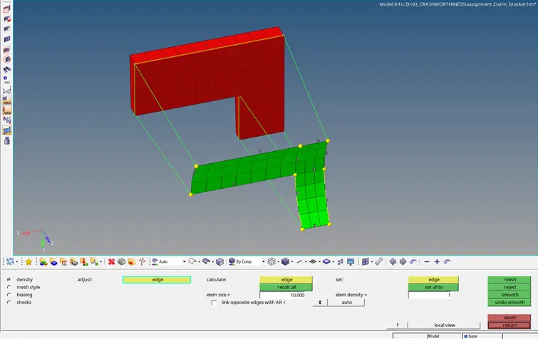
- Create solid elements from one face to other by Linear Solid panel.
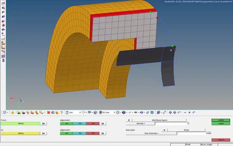
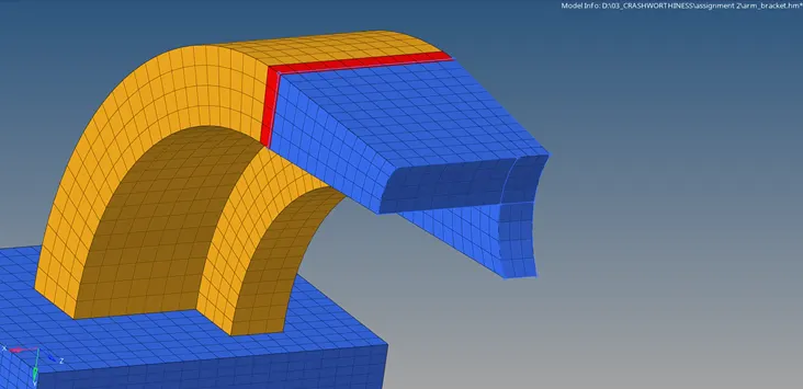
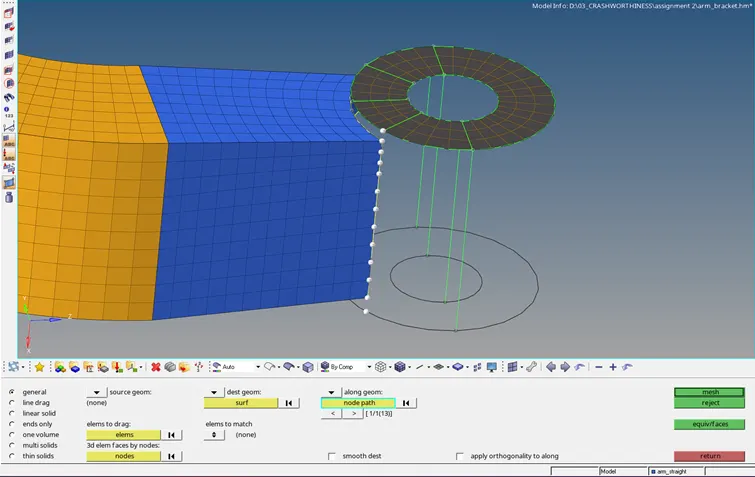
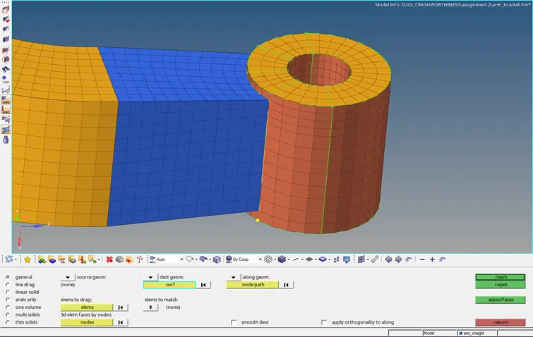
- Mesh the boss component by matching the nodes with arm straight mesh.
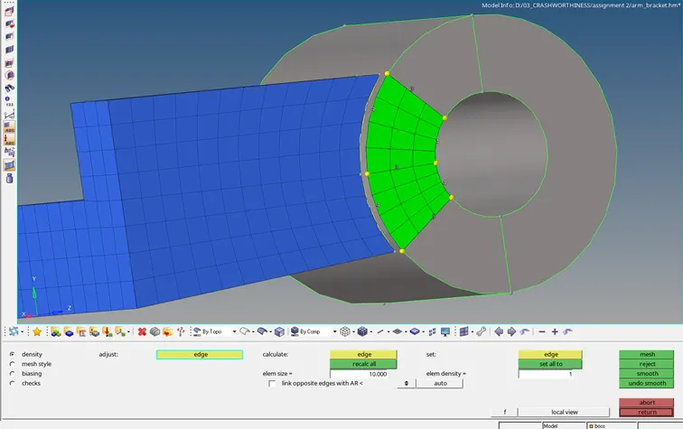
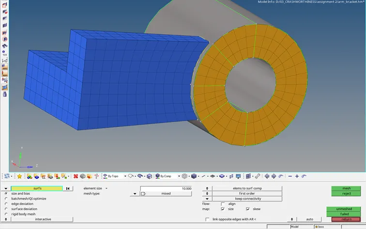
- Solid map the mesh to opposite face by selecting the the node path.
Final Model:
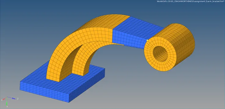
RESULT:
- The given models have been 3D meshed using hexa elements.