Assignment 2-RADIOSS Engine File Editing & 3D Meshing Challenge
Objective :
- The main objective of this Assignment is to understand the basic of the Radioss .
- Understanding of the Various file , which are needed for simulations .
- Understanding the meaning of the content written in the Radioss file .
- Calculation of the time step / Speed of the Sound .
- Editing the Engine file for monitering the stress wave traveling through the Steel Rail .
- Creating the 3D Mesh Tetra mesh and Hexa mesh on the given component .
- Checking 3D mesh created against the provided Quality criteria .
Q 1) Ans :
The Speed of the sound can be calculated using the formula as ,
C = ">√E/Rho
Here
C = Speed of the Sound
E =Young's Modulus ,
Rho = Density of the steel .
From the Radioss Starter file
Material properties for the Steel are
Rho = 0.0078 g/mm^3
E = 210000 Mpa .
Hence ,
C = √210000*0.0078
C = 5188.75 m/s
Speed of the Sound in Steel rail is 5188.9 m/s .
Q 2) ANS :
Length of the Steel Rail = 1000 mm = 1 m,
Speed of the Sound = 5188.75 m/s ,
Time required for shock wave = length of the Rail/Speed of the sound
T = 1/5188.75 = 0.197 mili-second
Q 3 ) Ans :
Time for sound to travel through the rail = length of the Rail / Speed of the sound
T = 1/5188.75 = 0.197 mili-second
Q 4) Ans :
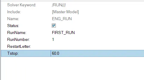
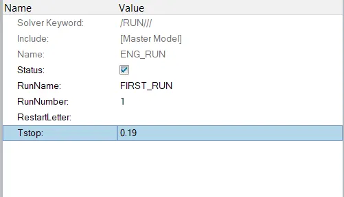
In RUN card the TStop ( Termination ) changed to the time required to travel the shock wave through the Rail .
Before After
Q 5 ) ANS :
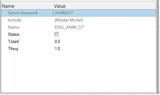
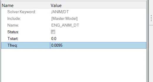
for setting the frequency of the animation output , we have to calculate the Frequency T = Run time / Noumber of steps
Freq. T = 0.19 / 20
Freq. T = 0.0095 Hz
Before : After :
Q 6 ) ANS :
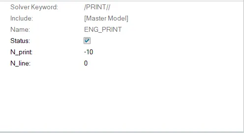
There is no need to change the priont value as there is already defined value is metioned to -10
3D Meshing :
Tetra Mesh :
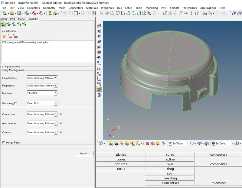
CAD Model :
Procedure :
- Initialy the FE model is imported using impote model Tool .
- Then 2D meshing are created using the Auto mesh - Geom Tool with Target Element SIze of the 5 mm .
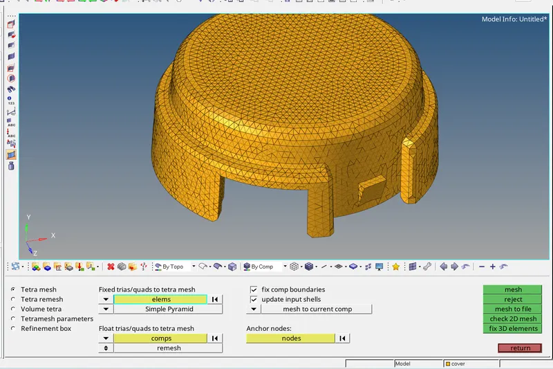
- Then Using that 2D shell elements 3D tetra mesh is created using the 3D tetra mesh - Tool as ,
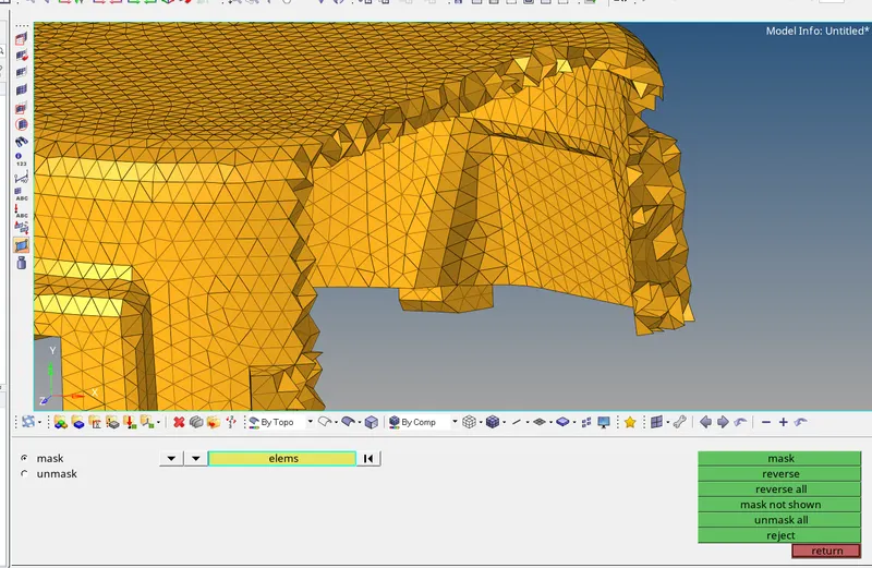
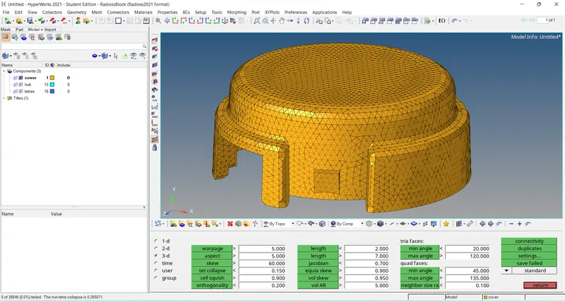
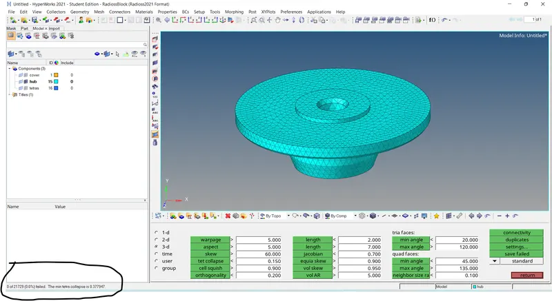
- Now Quality check for the Tetra mesh created is done by checking the Tet collaps can be seen below ,
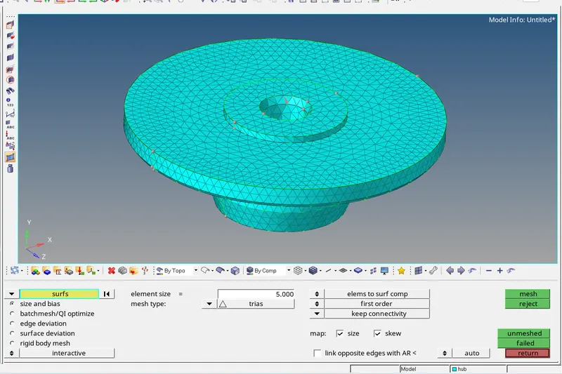
- Now for hub same procedure is followed for creting the 3D mesh as ,
2D mesh :
3D Tetra mesh :
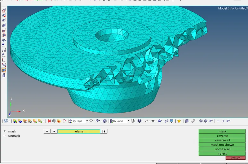
Tet collaps check :
Hexa Mesh :
CAD model :
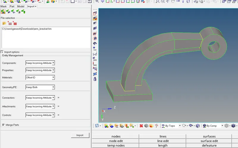
- Initially the Hexa mesh in base created .
- Firstly the 2D shell elements are created using the Automesh Tool with size of 10 mm and then using the Line drag Tool The hexa mesh created as .
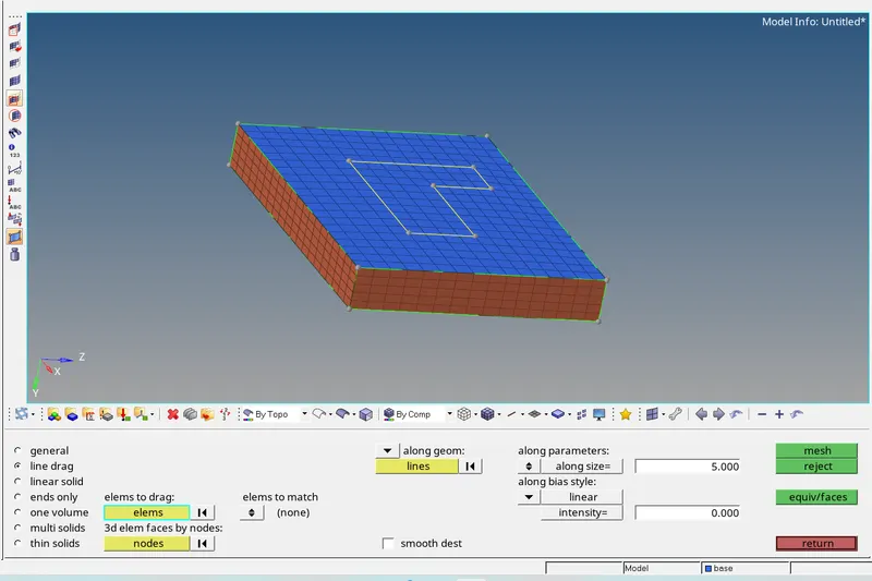
- Then For curve arm hexa meshing , we need to create the center node to use the spin Tool for creating the hexa mesh .
- This Node is created using the Arc centre Tool as ,
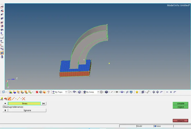
- Now using the Spin Tool The hexa mesh is created which can be seen below as ,
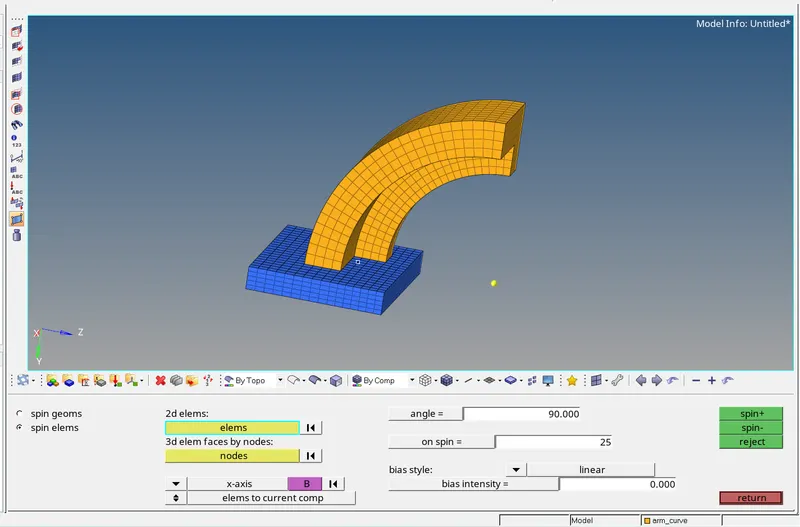
- Now for creating the hexa mesh in straight arm , we required the 2D shell elements to drag the elements for creating the hexa elements .
- hence 2D shell elements are creating the faces using the find faces Tool .
- And also on front surface 2D shell elements are created using the Auto mesh Tool .
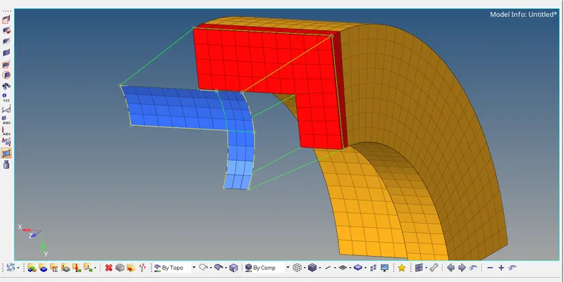
- using the Linear solid Tool the hexa elements are created as .
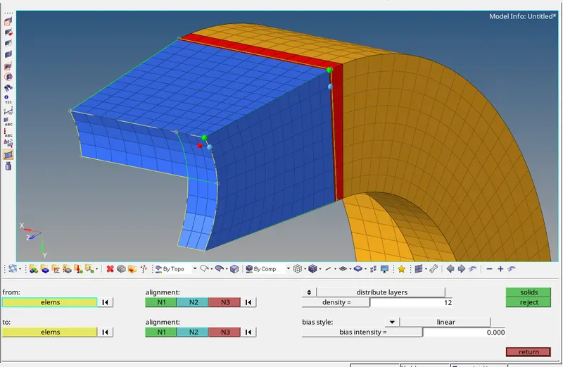
- Then 2D shell elements are deleted .
- Now for boss component , initially the 2D shell elements are created using the Automesh Tool on both side as ,
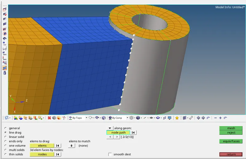
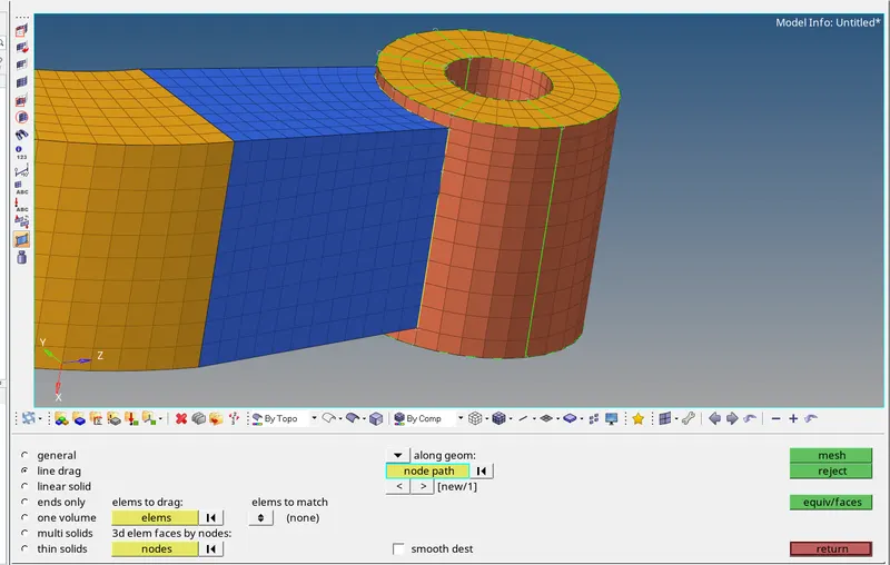
- Then using the Line Drag Tool along the nodes , the 2D shell elements are draged for creating the hexa elements are as ,
Result :
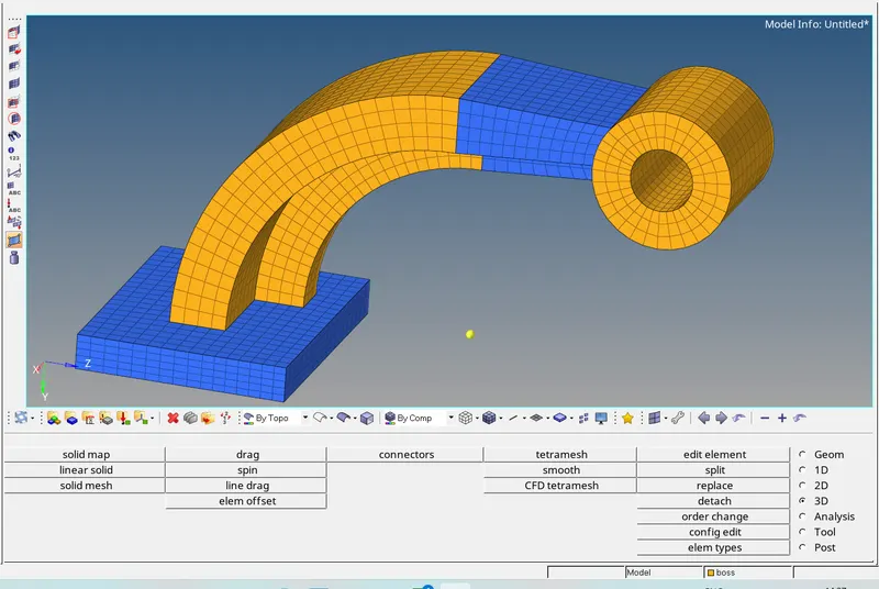
- The final model is ,