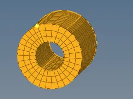
Assignment 2-RADIOSS Engine File Editing & 3D Meshing Challenge
Question
1. Check the material properties of the rail component and calculate the speed of sound in steel rail=_______
The speed of sound can be calculated by the equation below
C = `sqrt(E/rho)`
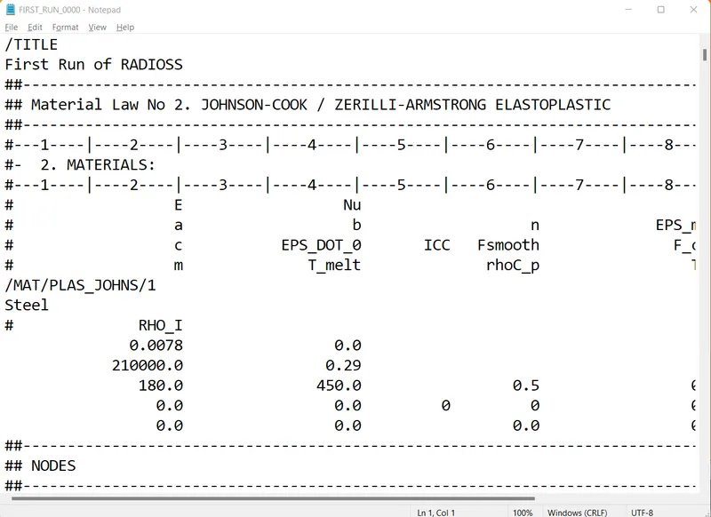
From the starter file given 0000.rad, we get the Density and youngs modulus of the steel rail.
`rho =`0.0078 `g/(mm^3)`
Young's modulus = 210Gpa or 210000Mpa
therefore, C = `sqrt`210000/0.0078
C = 5188.75m/s
Time taken for the shockwave to travel along the rail is given by the formula
t = l/c
t = 1/5188.75
t = 0.1927 (milliseconds)
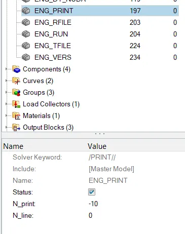
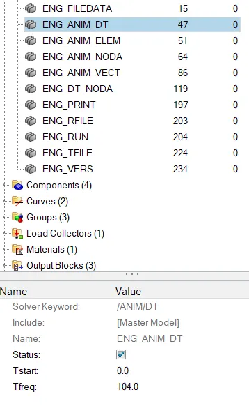
Frequency of animation Which will give 20 animation steps = (l/c)*time = (1/0.1927)*20 = 104hz
Procedure
1. First we import the solver deck FIRST_RUN_0000.rad file to hyperworks.
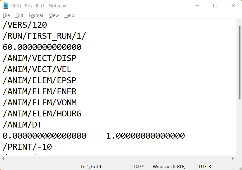
Below is the 0001.rad file which is not edited.
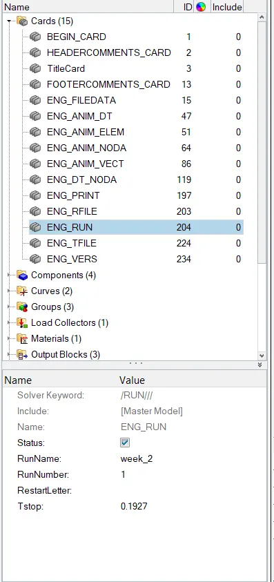
2. Now we make the changes which we have calculated above by clicking on Model>cards and then by clicking on the engine run, engine anim dat, and engine print cards and make the necessary changes.
--------------------------------------------------------------------------------------------------------------------------------------
--------------------------------------------------------------------------------------------------------------------------------------
--------------------------------------------------------------------------------------------------------------------------------------
--------------------------------------------------------------------------------------------------------------------------------------
--------------------------------------------------------------------------------------------------------------------------------------
--------------------------------------------------------------------------------------------------------------------------------------
3. Once this is done, we have to export this solver deck in .rad format. (the format will be automatically chosen by the computer.)
The 0001.rad file will be created and updated, below you can find the edited engine file
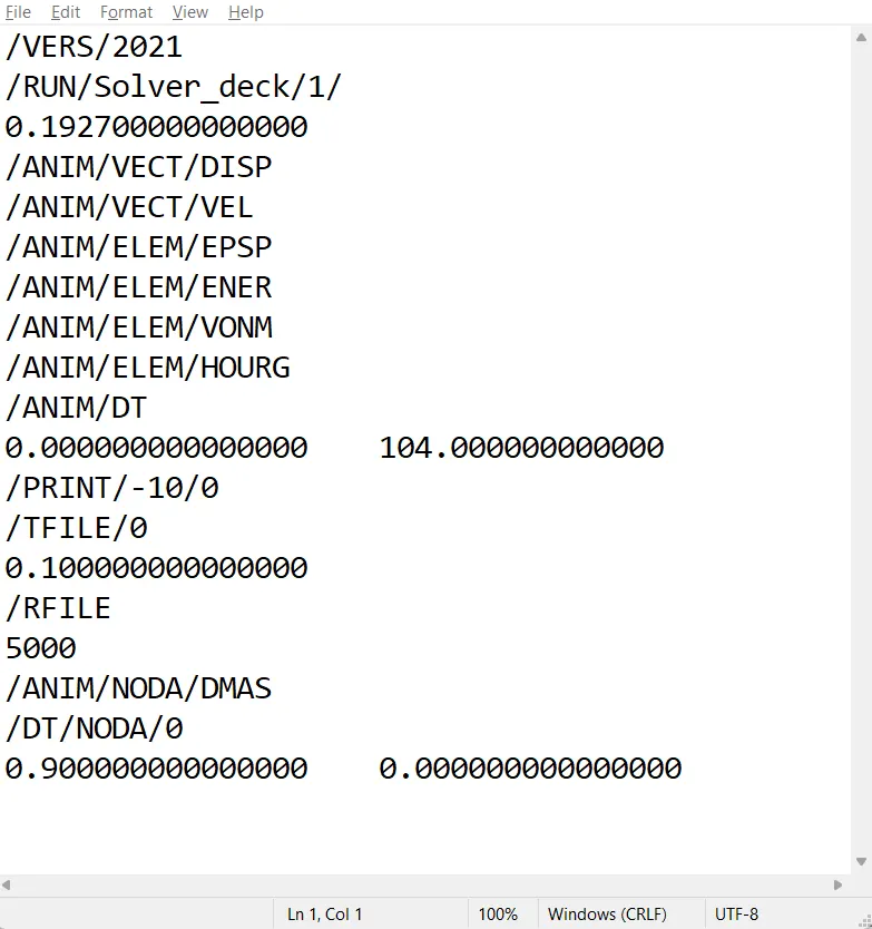
(solver_deck was the new file name that I saved. Hence the change in name )
3D meshing parts are below,
Part 1
Hub
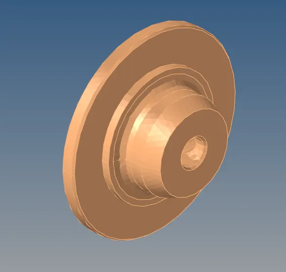
The meshing of the Above part-hub, was done in the following steps
1. First the Hub was made the current model
2. Auto meshing is done using element size as 10mm, set to trias.
3. once we get the 2d mesh which comprises tria, we convert It to 3d using tetra mesh in 3D tab.
4. choosing volume tetra, keeping tet collapse to 0.15, and hit mesh.
5. After successful creation of the 3d mesh which contains only tetras, we get the result below.
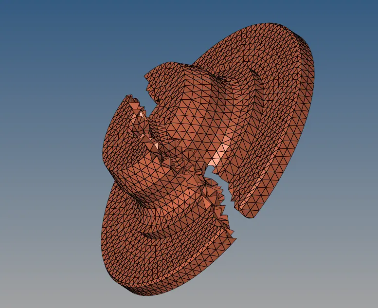

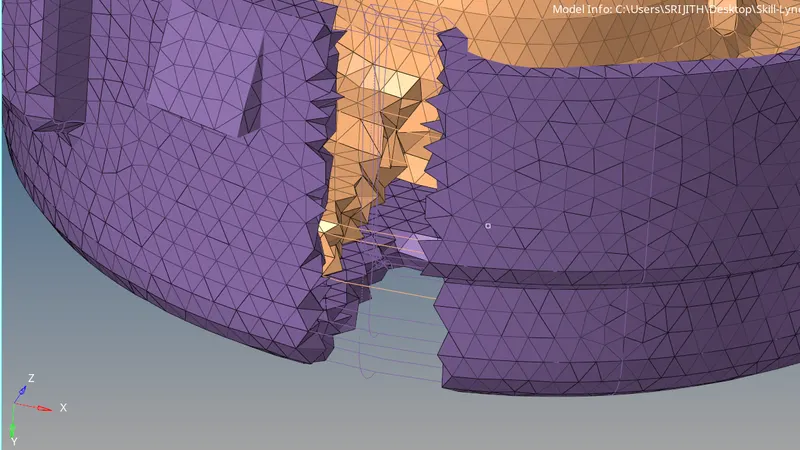
After masking a section of the part, we can see that there is a successful creation of a 3D mesh.
The element quality tab is given below
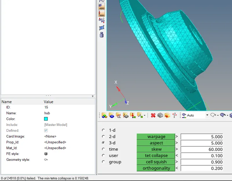
Moving on to Part 2
Cover
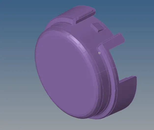
The same steps are repeated in meshing this part as well, with the following results
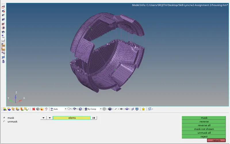
Tetra mesh successfully created, the the tet collapse value for the same is given below,
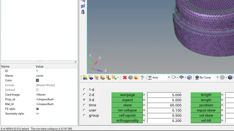
Here you can see the implementation of 3d tetra mesh in both the parts.
3D Mesh on an Arm Bracket
Base
1. First, we make the base as the current part, then we initially make a 2d mesh on the top surface.(elements size 10mm and type set to Quads)
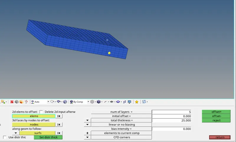
2. Then by using element offset, we create elements across the thickness of the base.(5 layers across 25mm thickness)
3. Since we require 2D elements to create mesh on the arm curve, we mask the 3d elements of the mesh.
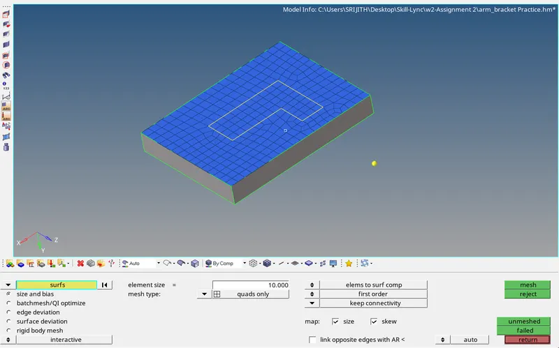
Element offset
Curved arm
1. With the curved section, we can use the spin elements command to create mesh along the curved arm.
2. Before we select the elements to be spun along the arm, we need to first, find the radius of the curve and find the center point
3. By clicking f4, we can use the 3 node option and find the circle center.
4. Moving on to spin elements, Select the ' L' shaped elements that need to be spun along the arm, 90 degrees angle for 2d elements, and 25 partitions, so on-spin will be 25.
5. For the spin axis, choose the x-axis, as the elements are spun along the X-axis.
6. The base node can be selected as the circle center node which was extracted earlier. Spin -, because of the angles, then you have a good 3d mesh in your curved arm part.
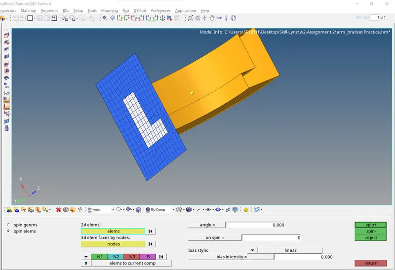
Spin elements
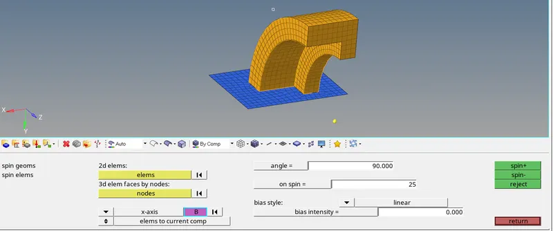
Arm straight
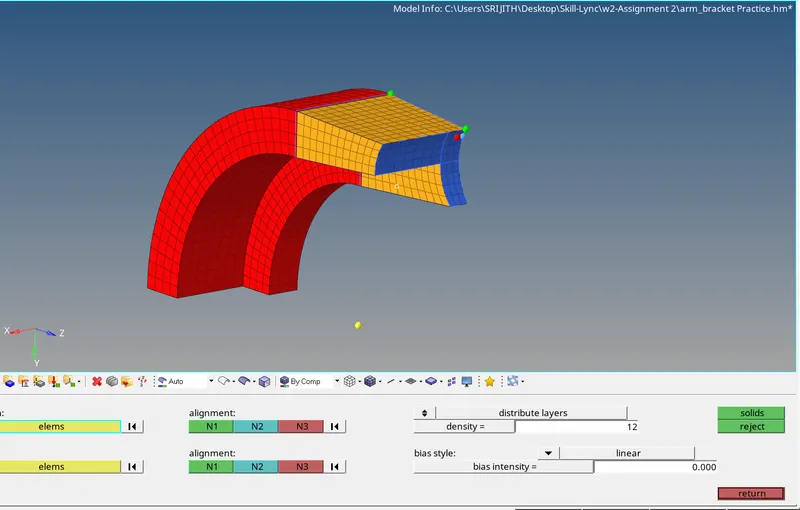
1. With this part, we are demonstrating how to use linear solid meshing in 3D
2. Initially we find 2D faces to help in defining the elements to be linearly created toward the end elements.
3. We mesh the outer end of the straight arm to give us a boundary till which the elements need to be created.
4. Bear in mind that the mesh in the end profile must have the same number and type of elements
5. With that taken care of now we select both the elements and align the mesh with the 3 nodes on each surface.
6. We create 12 layers and hit mesh.
Boss
1. The final part is the boss, the boss can be meshed using the solid map meshing command.
2. This requires a base mesh from which the mesh can be created.
3. We create a 2d mesh on one of the surfaces and then adjust the number of elements so that there isn't any errors in the mesh flow from the arm straight to the boss.
4. We then create a node at the end of the other side to which the mesh needs to be created.
5. After which we can use the solid map option, select the elements that were created on the surface and select the destination geometry, and for along geometry, use the node which was created as a path along the length of the boss and use another line to represent the boundary fo the elements