Assignment 2-RADIOSS Engine File Editing & 3D Meshing Challenge
AIM: (a) Utilise the given RADIOSS Engine and determine the responses
(b) 3D Meshing of the given model.
Questions:
1. Check the material properties of the rail component and calculate the speed of sound in steel rail=_______
Answer: Data from the Starter file
File Name: FIRST_RUN_000.rad
Dimensions: g(mass) mm(length) ms(time) N(Force) MPa(Pressure) N-mm(Energy)
Material Properties:
`rho =0.0078 g/(mm^3)`
`E = 210000MPa`
Now to determine the speed of sound in the rail component, we have
`Speed of Sound (c) = sqrt(E/rho)`
`c = sqrt(210000/0.0078`
`c = 5188.74 (mm)/(ms)`
2. The length of the rail is about 1000 mm. Calculate the time takes for a shock wave to travel from one end of the rail to the other.
Answer:
`time(t) = l/c`
`t = 1000/5188.74`
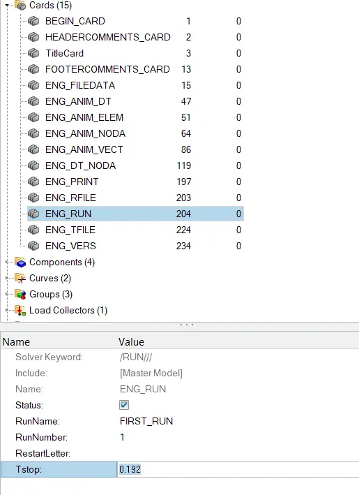
`t = 0.192 ms`
3. Time for sound to travel the length of rail= 0.19ms
4. Edit the engine file so that the stress wave can be monitored, moving from one end of the rail to the other during an impact -this will require a termination time equal to the time it takes for the sound to travel the length of the rail(set on/RUN card)
Answer:
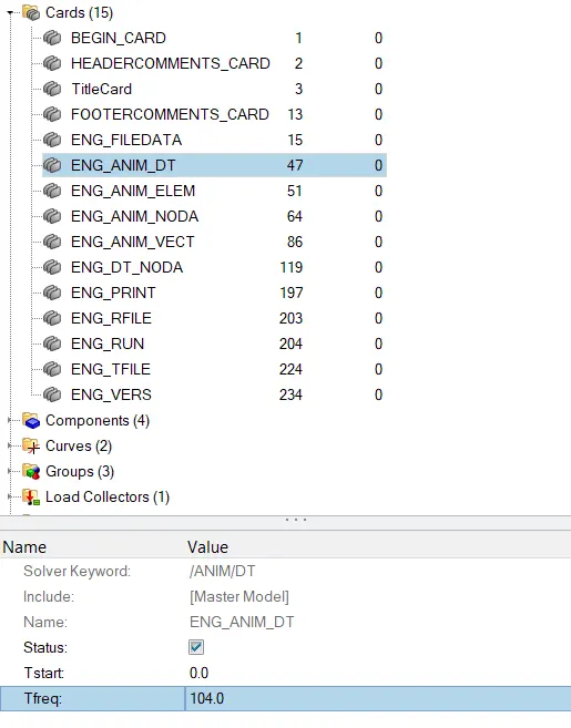
5. Set the frequency of animation output to a time that will give 20 animation steps(/ANIM/DT)
Answer: To determine the frequency, the termination time needs to be divided into 20 equivalent steps, thus we get
`=(20/0.192) ~104`
6.Change /print -10 this was determined by default in the given file.
7.3d meshing tetra mesh and hex mesh
Solution:
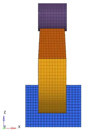
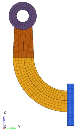
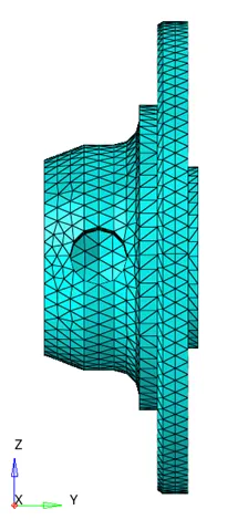
Hex Mesh of Arm Bracket
Procedure
- Initially, the base of the Arm Bracket was selected for meshing.
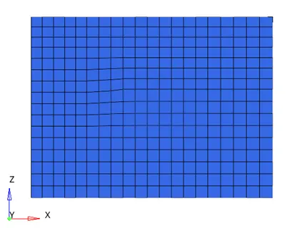
- 2D meshing was done on the surface using F12 key.
- The 2d mesh was converted to 3d mesh using the Solid Map option.
- For the curved section, the centre of the curve was determined using the 3 point distance measuring tool. then the spin option was utilised to spin the elements along the defined curve.
- Then faces were generated on the generated mesh to utilise to mesh the tapered section.
- The same number of elements were used to create 2D mesh on the connecting surface
- Then, the solid map option was used to generate the mesh along with the geometry.
- Finally, in the head section, the nodes were placed to follow the mesh pattern and the continuous mesh was carried out.
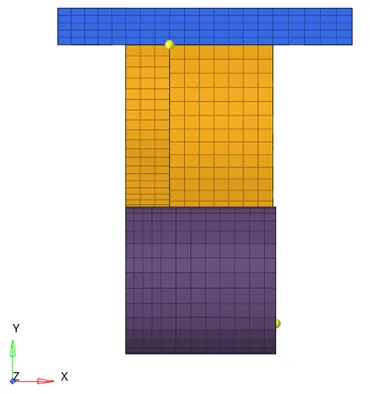
2D tet mesh of the cover
Procedure
- Firstly the cover was meshed using a simple mesh option using tet elements with an element size of 5mm.
- Then 3D mesh was generated along the geometry using the 2D tet mesh generated.
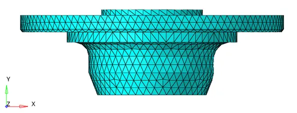
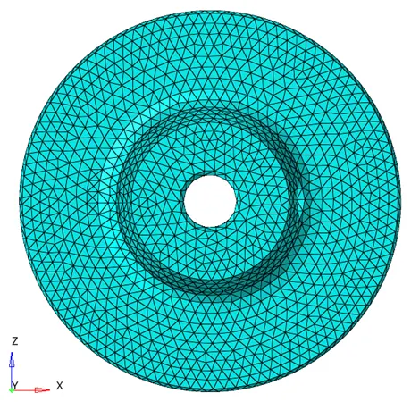

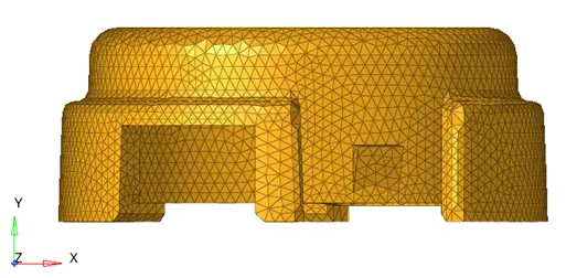
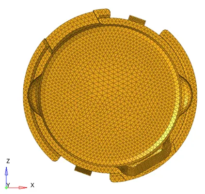
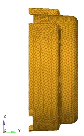
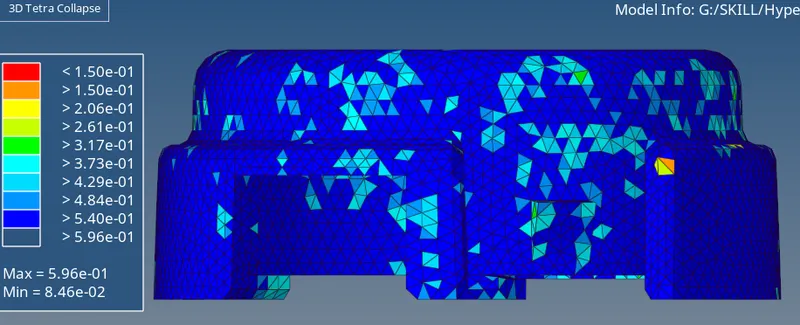
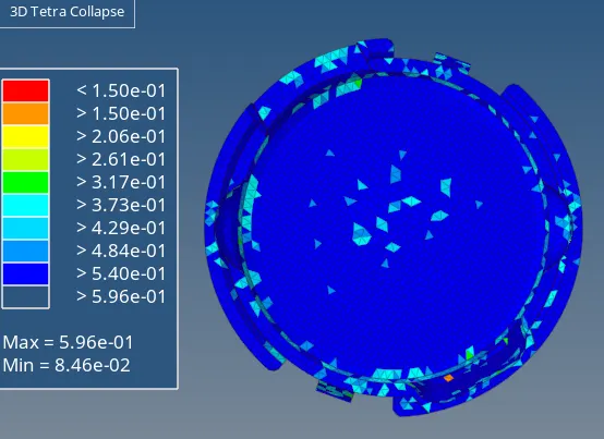
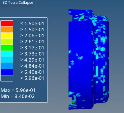
In the other section, directly 3D tet mesh was generated and the 3D tet mesh quality conditions were defined.
3D Tetra Collapse
CONCLUSION
- The given models were meshed using 3D elements with Tetra and Hexa elements.
- In the other section the formulation was utilised and the time step was calculated and implemented in the RADIOSS.