Assignment 2-RADIOSS Engine File Editing & 3D Meshing Challenge
1. Check the material properties of the rail component and calculate the speed of sound in steel rail=_______
So to check the material properties of the material of the rail component. We have to import the component in the hypermesh.
We have the ".rad" file. So for that, the profile should be RADIOSS.
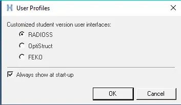
Now we will go to the import option. There we are going to select the 0000.rad file and import it.
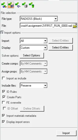
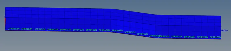
Now we will go to material property and check the values.
Speed of sound (c) = `(E/rho)^(1/2)`
where E = Young's modulus
`rho` = density
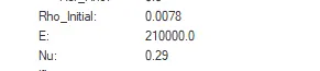
So speed of sound (c) = `(21000/.0078)^(1/2)`=5188.745 m/s
2. The length of the rail is about 1000 mm calculate the time takes for a shock wave to travel from one end of the rail to the other.
Shock wave travels at the speed of sound. So
shock wave speed = speed of sound = 5188.745 m/s
time (t) = `("Distance"(D))/("Speed of shock wave")`
t = `1000/5188.745 = 0.1935`s
3.Time for sound to travel length of rail=______
time (t) = `("Distance"(D))/("Speed of sound"(c))`
t = `1000/5188.745 = 0.1935`s
4. Edit the engine file so that the stress wave can be monitored, moving from one end of the rail to the other during an impact -this will require a termination time equal to the time it takes for the sound to travel the length of the rail(set on/RUN card)
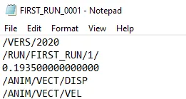
We have to give the end time to be 0.1935s. There are two way by that we can do that.
(i). First is just open the 0001.rad file and edit the end time value in the file
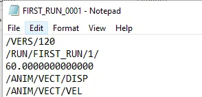
After giving the value
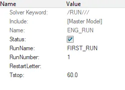
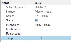
(ii). In the second method, we change the value in the hypermesh itself. There we go to the ENG_RUN card. There we change the Tstop value. There we have to give the value to be 0.1935 and after that we have to run the file. So it will change the values in the 0001.rad file itself.
After giving the values
To run the files we will go to the Analysis--> RADIOSS

Here we now save the file into a new folder and after that, we will click on the Radioss. It will run the file.
And we will get the job done message
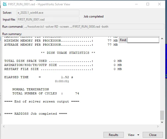
After running the file
5. Set the frequency of animation output to a time that will give 20 animation steps(/ANIM/DT)
frequency = `(time)/("no. of revolution") = 0.1935/20 = 0.009675`
So to change this value. We have two methods
(i). First is just open the 0001.rad file and edit the end time value in the file
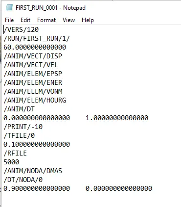
After giving the value
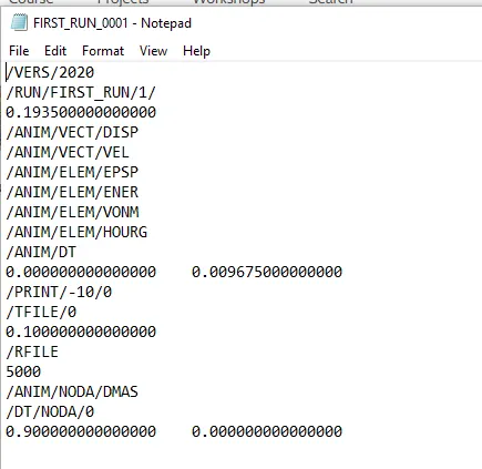
(ii). In the second method, we change the value in the hypermesh itself. There we go to the ENG_ANIM_DT card. There we change the Tfreq value. There we have to give the value to be 0.009675 and after that we have to run the file. So it will change the values in the 0001.rad file itself.
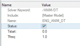
After giving the values
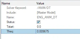
To run the files we will go to the Analysis--> RADIOSS
Here we now save the file into a new folder and after that, we will click on the Radioss. It will run the file.
And we will get the job done message
After running the file
6.Change /print -10.
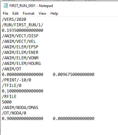
We can see that the by default PRINT value is 10. So there is no need to change that.
Create a Teramesh for Housing component
Quality Criteria:-
Target tet size=5mm, Tet collapse: 0.15
1. First we are going to import the model.
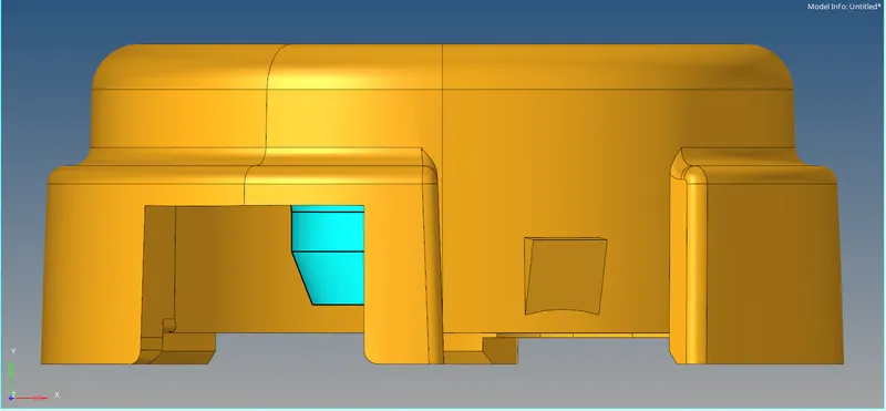
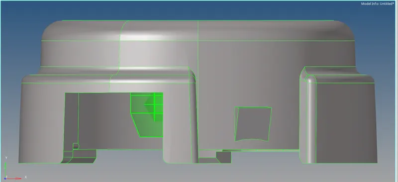
2. First we are going to delete the solid from the component.
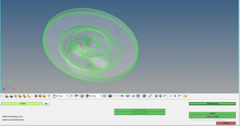
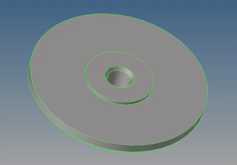
3. We are going to give the criteria file setting.
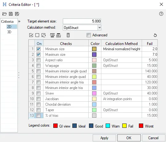
4. Now we are going to do the geometry cleanup. We check the areas where if we mesh it fails for the quality criteria and according to that we are going to do the changes in the geometry.
5. Now we are going to do the 2-D meshing with the trias on the surface of the component.

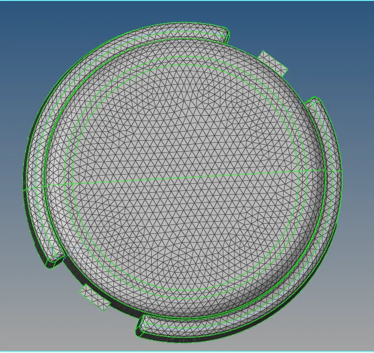
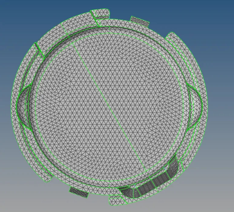
We have to make sure that it is not failing for the quality criteria.
6. Now we are going to create the tetra meshing with the 2-D elements. So for that, we are going to go the 3-D--> tetramesh.

Here we are going to select the 2-d elements and then we are going to click on the mesh.
7. Now we want the tet collapse to be less than 0.15. So we are going to check that from the check elements. In that, we are going to the 3-d and we are going to give the value of tet collapse to be 0.15 and we are going to check that how many of the elements are failing for the tet collapse.
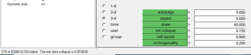
So 275 elements are failing for the tet collapse.
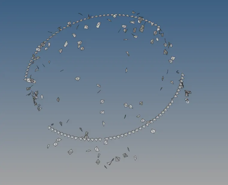
8. To remove the tet collapse we are going to do the tetra remesh. So again we go to the tetramesh and we are going to give the Tetramesh parameter and there we are going to give the tet collapse to be 0.15. There we can also give the maximum and minimum tetra size.

9. Now we are going to do the remesh.

10. After that we check the tet collapse again in the mesh and check that if any elements are failing for the tet collapse.
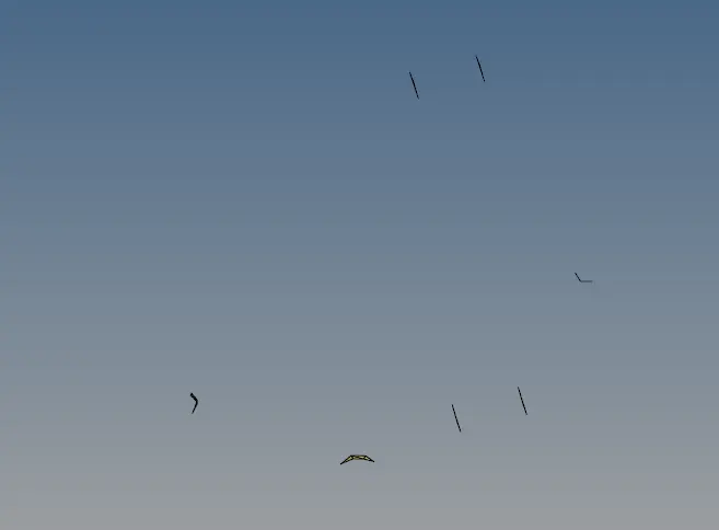
Some of the elements are failing for the tet collapse. Which we have to remove manually. So for that, we will go to the distance tool. and change the distance between two nodes of the tetra element and remove all the tet collapse failure.
11. 3-D tetra mesh is complete in one component of the model.
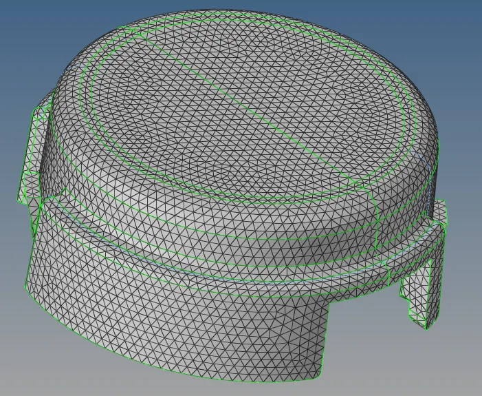
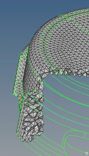
12. Now we follow the same process for the second component.
13. The component has some issues that we have to solve by the geometry cleanup.
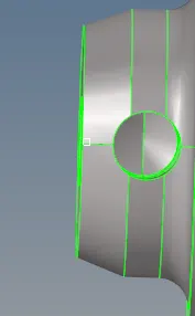
The hole should be proper in the component. So we are going to create a hole in the surface.
14. So for that we are going to trim the surface by the lines and we are going to delete that surface.
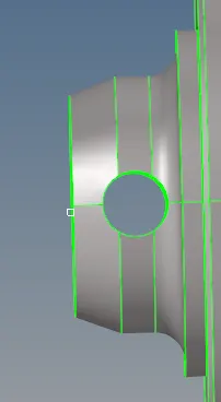
Now we have the proper surface to create the 2-D mesh.
15.Now we are going to do the 3-D tetramesh.
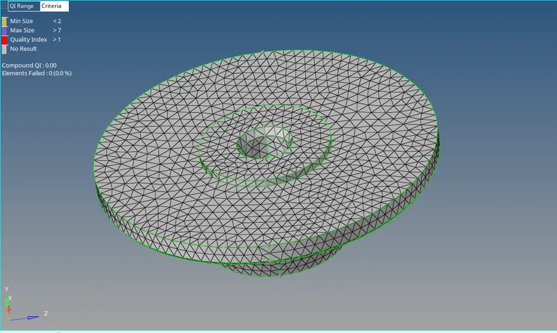
Checking for the tet Collapse.
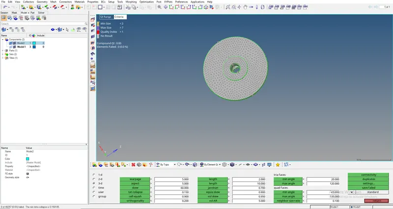
No elements are failing for the tet Collapse.
16. Now we are going to delete the 2-D elements from the component.
Create a Hexamesh for Arm Bracket component
Quality Criteria:-
hex size= 10mm
1. First we are going to import the model.

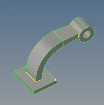
2. Now we are going to do the geometry cleanup. We check the areas where if we mesh it fails for the quality criteria and according to that we are going to do the changes in the geometry.
4. Now we are going to do the hexa meshing on the component. We are going to create the 2-D meshing on the component and then we are going to convert 2-D element into the 3-D element.
5. First we are going to mesh on the base of the arm bracket.
Now we are going to do the 2-D meshing with the quads on the surface of the component.

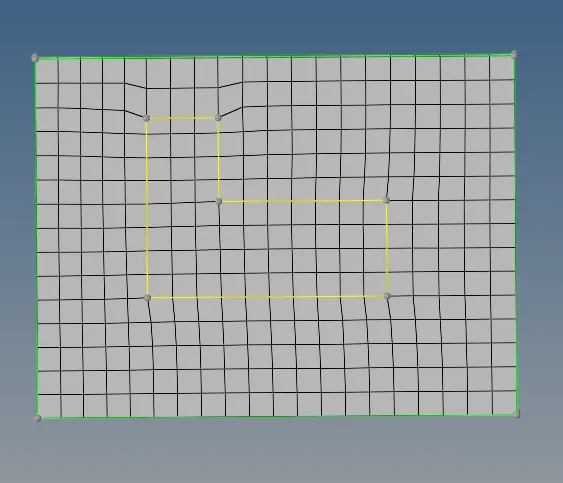
Now we are going to convert these 2-D elements into 3-D elements. For that 3-D--> element offset

So we are going to select 2-D elements and then we are going to select the surface where we are going to offset the elements.
So after offset, the mesh will be like this:-
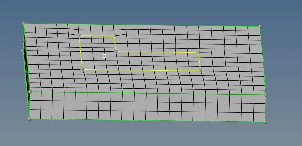
6. Now we are going to mesh the arm curve. So again first we are going to create 2-D mesh and then we are going to convert that into the 3-D mesh.
But we have to keep it in mind that the element on the cross-section area of the arm curve should be equal to the elements which are present on the base (same cross-section area).
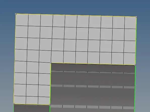
With the same no. of elements we are going to mess the other cross-section of the arm curve.
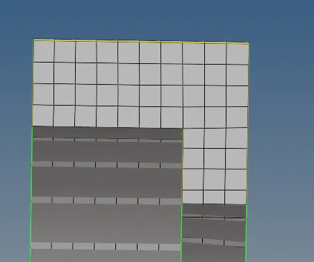
Now to convert these 2-D elements into 3-D elements. We will go to 3-D--> spin

So we are going to need the base point to convert 2-D elements into 3-D. So for that we will go to Geom-->nodes

Now we will go to 3-D--> spin and we are going to give the angle to be 90 and we are going to make hexa mesh.
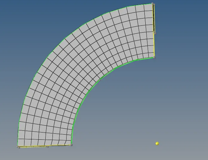
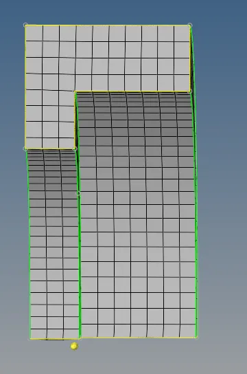
7. Now we are going to mesh the arm straight. So again first we are going to create 2-D mesh and then we are going to convert that into the 3-D mesh.
But we have to keep it in mind that the element on the cross-section area of the arm straight should be equal to the elements which are present on the arm curve (same cross-section area).
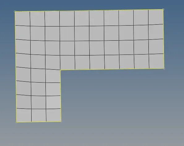
With the same no. of elements we are going to mess the other cross-section of the arm straight.
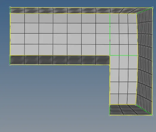
Now we are going to convert these 2-D elements into 3-D elements. For that 3-D--> solid map

So the mesh will look like this
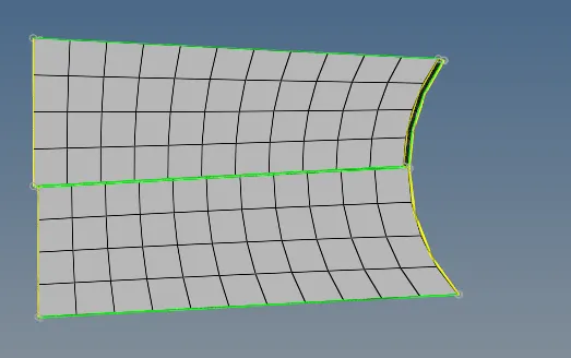
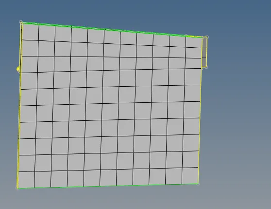
8. Now we are going to mesh the boss. So again first we are going to create 2-D mesh on the cross-section area of the boss and then we are going to convert that into the 3-D mesh.
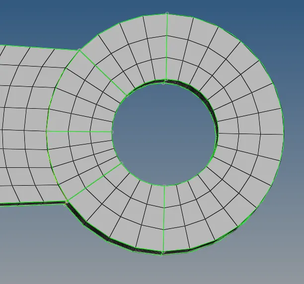
Now we are going to convert these 2-D elements into 3-D elements. For that 3-D--> solid map

So the mesh will look like this
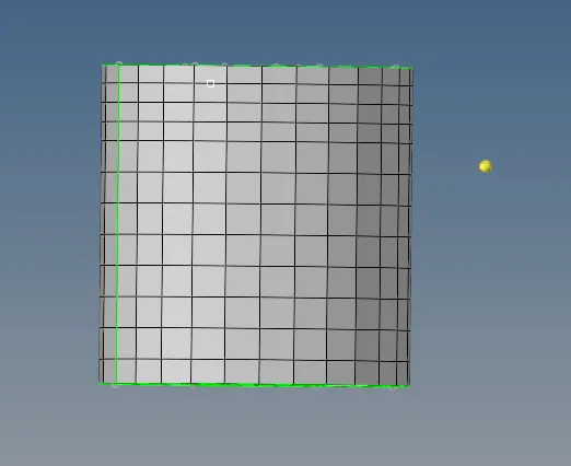
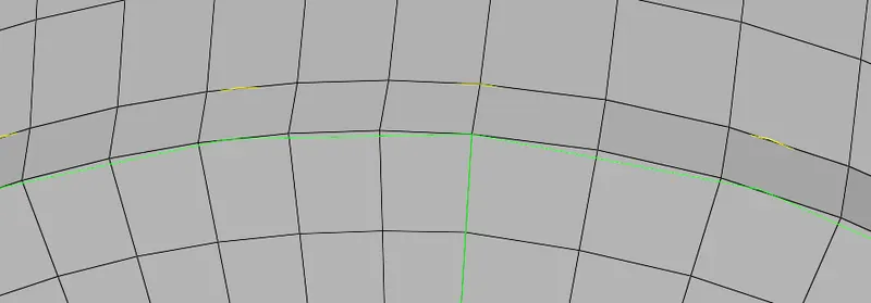
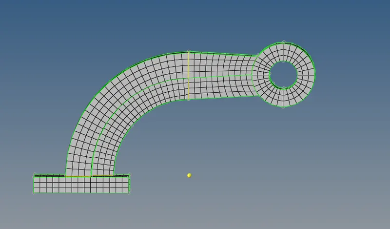
9. Now we are going to check the connectivity of the elements. We need to make sure that should not be any free edges present in the mesh.
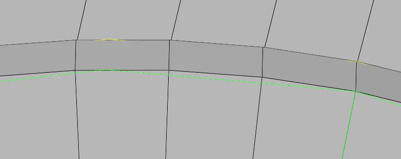
So there is some connectivity issue in the meshing. So we are going to manually resolve this issue. So after connecting those nodes the mesh will look like this.
10. Now we are going to delete the 2-D elements from the component.
Learning Outcome:-
1. Learn to create 3-D meshing.
2. Learn how to create Tetra Mesh And Hexa mesh.
3. Learn about the tet collapse.
4. Learn about the RADIOSS files.
5. How to run the simulation in the RADIOSS.
6. Learn about the time step, end time and how to calculate these.