Assignment 2-RADIOSS Engine File Editing & 3D Meshing Challenge
Aim: To create the rad file of the rail component and work on the 3D meshing for given models.
Questions:
1. Check the material properties of the rail component and calculate the speed of sound in steel rail?
Ans; Elemental Time step Δtc = (l/c)=(l/√(E/⍴)
Considering the equation,
C=√(E/⍴),
Here ,E=Young's modulus.
rho=density.
From material properties of rail component,
c=√(210000/0.0078)
c=5,188.74
2. The length of the rail is about 1000 mm.calculate the time takes for a shock wave to travel from one end of the rail to the other?
Ans; Time step, Δtc = (l/c)=(l/√(E/⍴)
Δtc=l/c
Δtc=1000/5188.74
Δtc=0.1927
3.Time for sound to travel length of rail
Ans; Δtc=0.1927
4.Edit the engine file so that the stress wave can be monitored, moving from one end of the rail to the other during impact -this will require a termination time equal to the time it takes for the sound to travel the length of the rail(set on/RUN card)?
Go to the file >import>solverdeck>import the model.
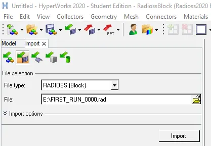
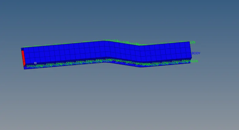
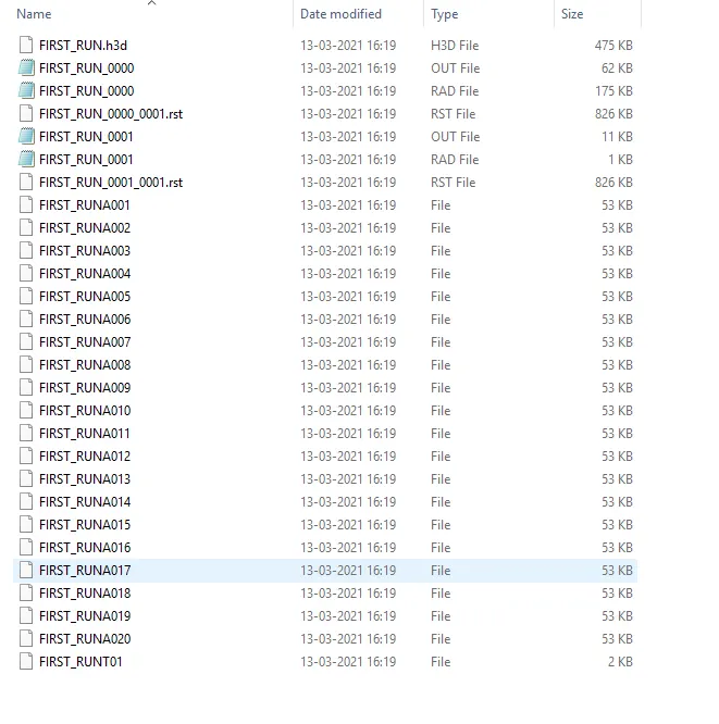
The model having an cards and where we change engine animation frequency and engine run .
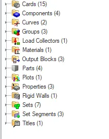
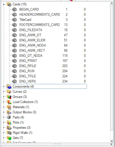
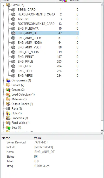
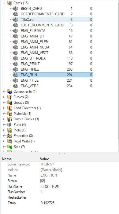
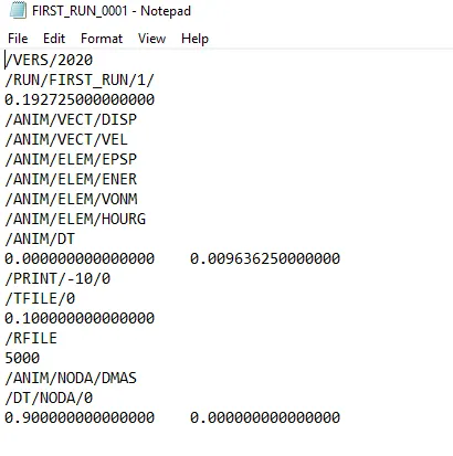
Here we see the results of output radfile and changes of the output is seen in the below fig.
5.Set the frequency of animation output to a time that will give 20 animation steps(/ANIM/DT)
Ans; f=Termination End time / Steps Required
f=0.1927/20
f=0.009635
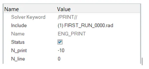
6.Change /print -10.
7.3d meshing tetra mesh and hex mesh
- Repeat class examples and, maintain the quality.
- Target tet size=5mm,hex size=10mm,tet collapse=0.15.
3D MESHING;
3D meshing is a process used in Hypermesh software, used to mesh the components which have thickness more than 5 or 6mm and do not have uniform thickness throughout the component. There are 2 types of the meshing process.
i) Hexa meshing.
ii) Tetra meshing.
HOUSING MODEL;
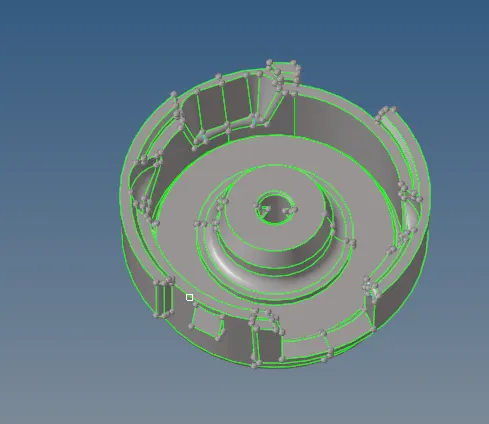
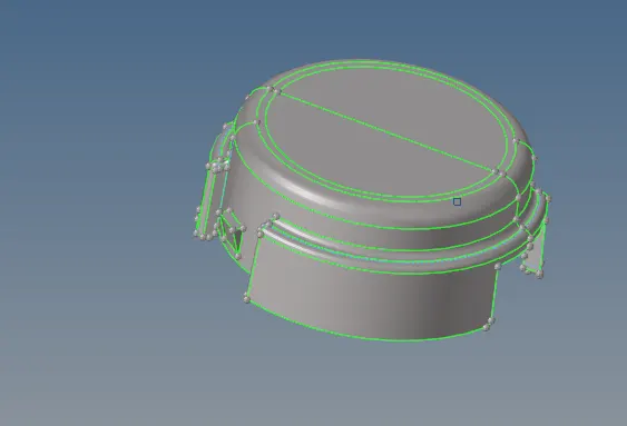
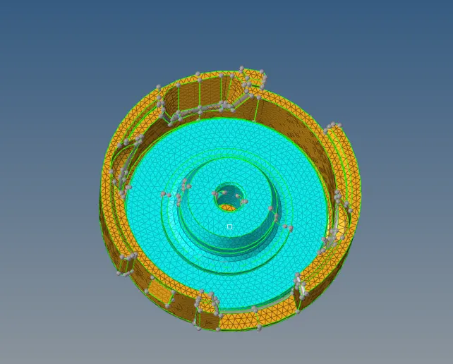
1.Now go to the 2d panel and create a 2D mesh with tria elements of target length of 5mm for the model.

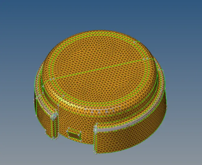
Now go to the 3d panel Set the tetramesh parameters for the tet collapse, minimum and maximum element sizes for the model.


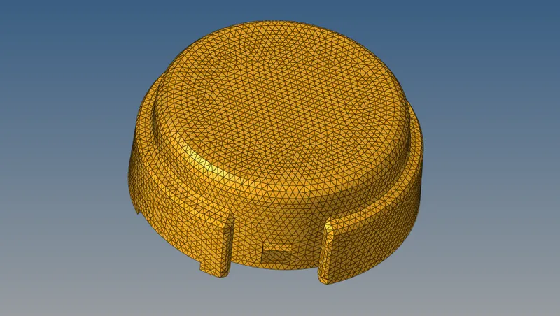
After setting the parameters, mesh the component by selecting the component. To check the volume mesh created in the component, mask the 2D elements on the surface to view the 3D mesh elements.

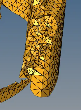
Go to quality index and check for the tet collapse of the 3d model.


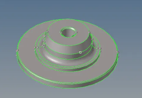

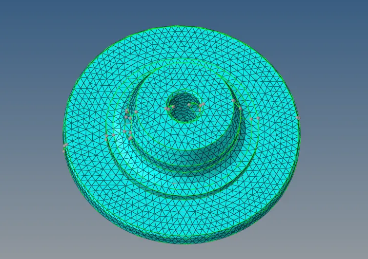
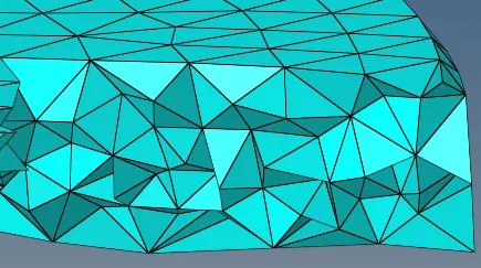
Go to quality index and check for the tet collapse of the 3d model.
ARM BRACKET;
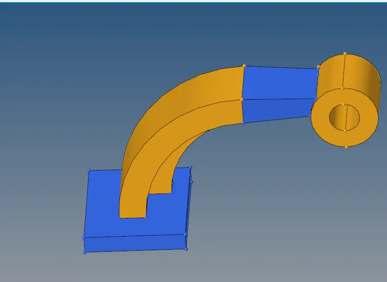
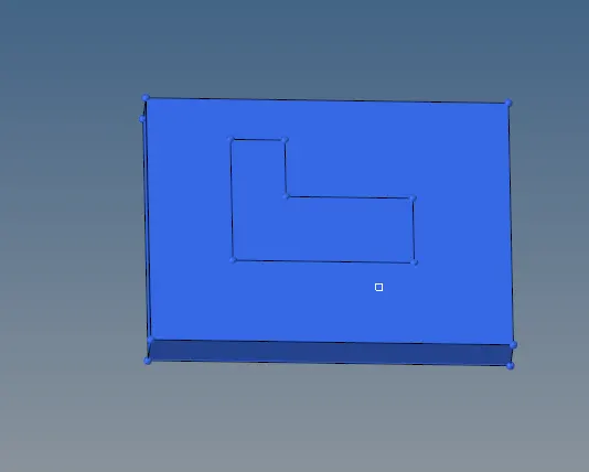

The base of the arm bracket is meshed with an 2d mesh elements with an target element 10 mm.
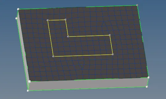

Now go to the 3d panel and where select the element offset >solid layers >num of layers>total thickness.

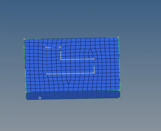
Now go to the mask>by config>mask the elements.

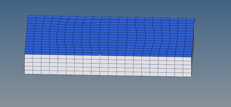
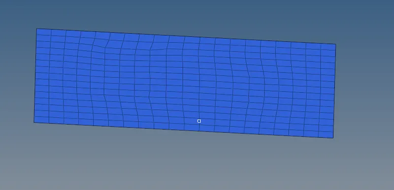
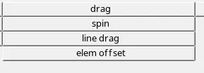
Next spin the elements from the base part to arm curve.
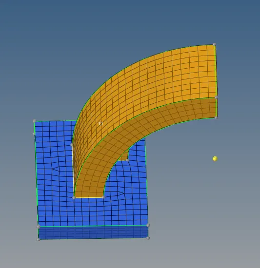
Go to tool >faces >add faces to the surfaces > which is used to clear view of the geometry.
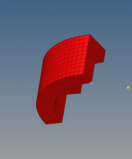
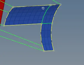
Linear solid
In this elements and alignment are selected from to the destination elements to form an arm straight.

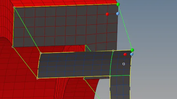
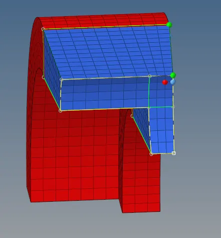
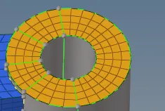
By using the project option we duplicate the node and project at the end of the surface of the boss.

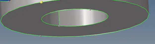
drag the all the elements to the entire boss.
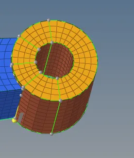
Delete the shell elements >by config>quad4>delete the 2d elements.

Move the boss in to the original component.
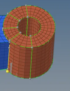

CONCLUSION;
create the rad out files and generate the 3d mesh on the given models.