Assignment 2
1. To calculate the speed of sound in steel rail
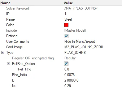
We know that Speed C = sqrt(E/Rho)
where C = speed of sound
E = Youngs Modulus
Rho= Density of Material .
C= sqrt(210000/.0078) =5188.745 m/s
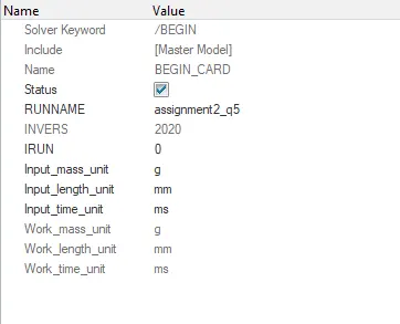
2. & 3.
Given : Length of rail L = 1000mm
To find time of shock wave to travel length of rail.
We know that T= L/C
T= Elemental time step
L= Length of element
C= Speed of sound in that medium .
Hence T = 1000/5188.745 = 0.192 ms
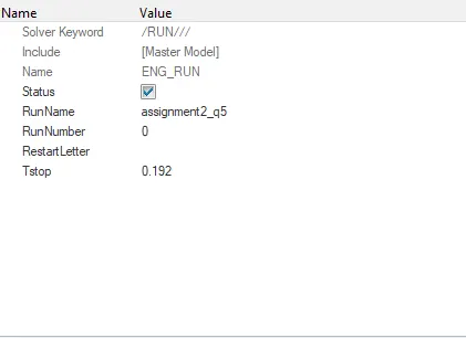
4. To edit the RUN card , the solver deck was imported to hypermesh .The value of elemental time step calculated earlier was entered to Run card .
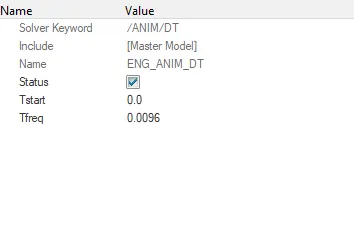
5. To set frequency of animation ,
We know that Tf = T elemental/ No of animation steps
Where Tf= frequency
Hence T = 0.192/20 = 0.0096
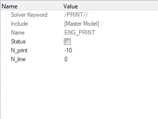
6. To edit the Print value to -10
Go to the Engine Print card , click on N_print value , enter as -10 .
7.
Objective : To 3D mesh the given arm component and Housing component according to given criteria .
Housing Component
Procedure :
The given model was imoprted and visually inspected for surface deformations .
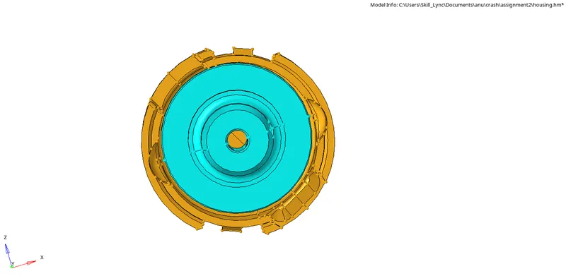
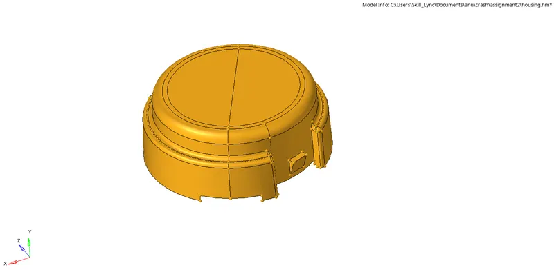
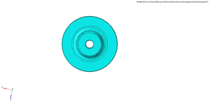
There are 2 components in the housing model .
They were selected and meshed seperately . The procedure for both remains the same . Hence the procedure shall be explained as one .
The surfaces were selected and volume tera option from 3D module was used to mesh the entire component .
The use curvature and use proximity option were ticked on along with clean up elements option .
The target element size was entered to 5 as per given criteria .
The 2D element type were selected as trias .
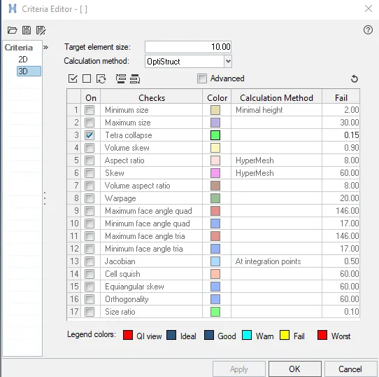
In the criteria file settings , the tet collapse value was entered to be 0.15 .

Hence the two components were 3D meshed . Mask elements option were used to check for elements inside surfaces .
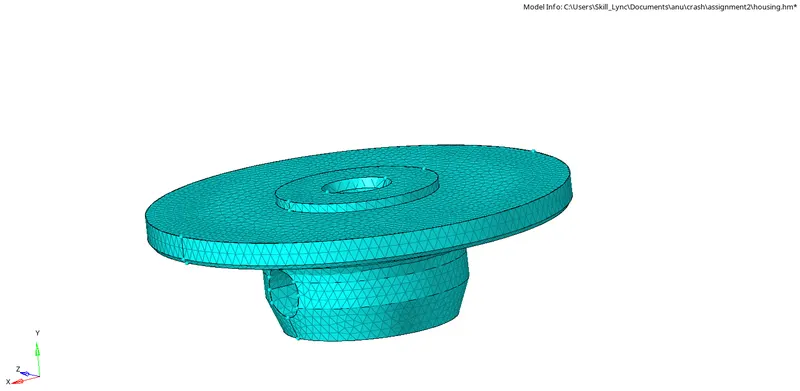
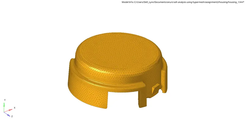
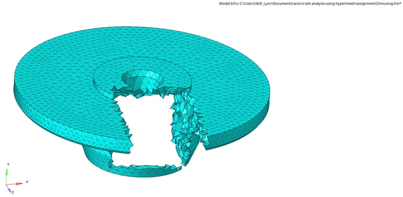
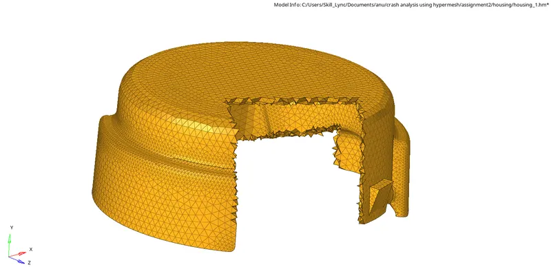

The element quality check for tet collapse was checked using check elements option and was found to be 0 .

Conclusion : Hence the model was 3D meshed with tetra elements as per given quality criteria .
Part 2 : Arm bracket
To Hexamesh the arm bracket model , the model was imported and visually inspected for surface deformations .
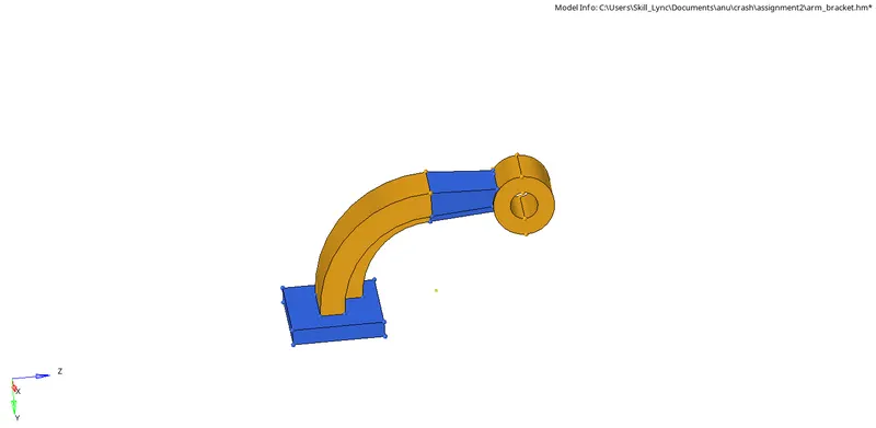
To perform hexa mesh , the base component was chosen with all other components hidden .
Automesh option from 2D panel was opened , element size was entered to 10 as per given criteria .
The mesh type was chosen to be quads only . and the top surface of base component was meshed to form quads only .
The rotating quads formed were remeshed and trias formed were cleared using clean up tools from quality criteria .

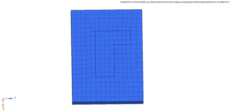
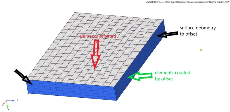
To make this to a 3d Hexa mesh , solid layers from element offset of 3D module was chosen .
The elements to offset was selected , the surface geometry to follow was selected . The number of layers were selected as 5 as total thickness was 25 units .
Offset was clicked on to create hexa mesh on the component.
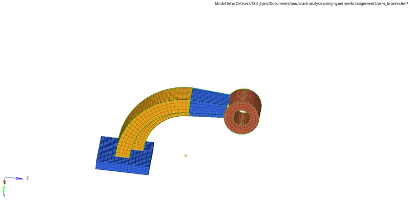
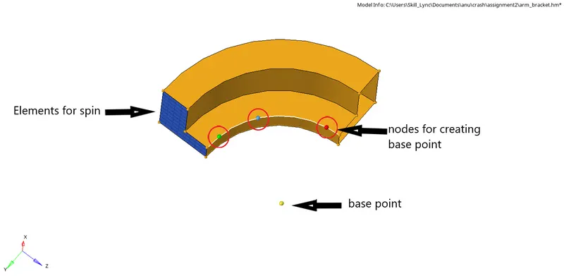
Meshing for the curved component was performed by using spin function . All unrequired elements were masked and a central node for spin function was created by using three nodes option from distance dunction of geometry module . The temp node thus created was selected as base point for spin about x axis . The ements on spin was chosen as 25 , and angle was chosen as 90 degrees .

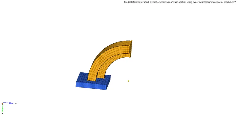
Thus hexa elements for curved component was also created .
For the arm straight component , linear solids option was used to create hexa mesh . Face option was used to create a component with elements at every face of curved arm component . The opposite face of the arm straight component was 2D meshed to make equivalent element number to match the adjacent face of the curved component . The density was selected as 12 . The nodes were selected at exact element of opposite surface .
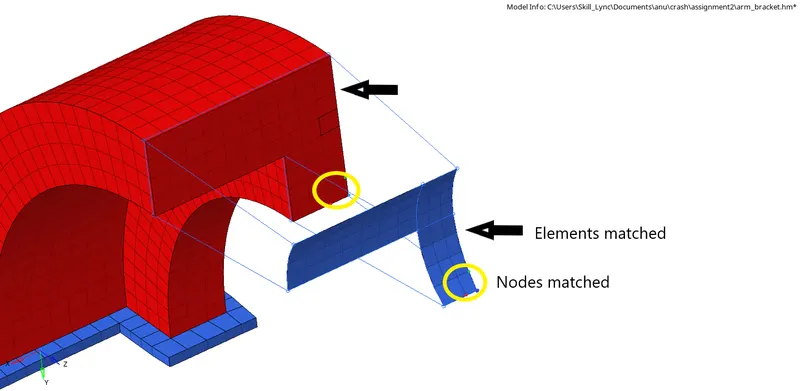

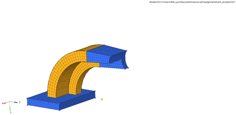
Hence hexa elements for straight arm component was created .
The face component was deleted along with other 2D elements using delete dunction.
To create Hexa mesh for Boss component , general option from solid maps function of 3D module was selected . The circular surface of boss was 2D meshed using Automesh . A temporary node was projected onto the base surface project node to surface option. The source geometry , destination geometry , node list and elements were selected . Hence the Hexa mesh for boss component was created as an additional component .

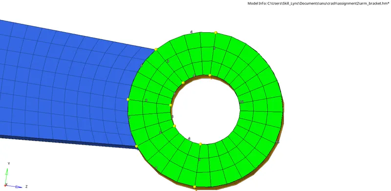
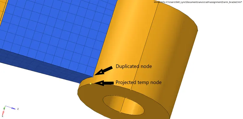
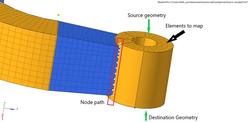
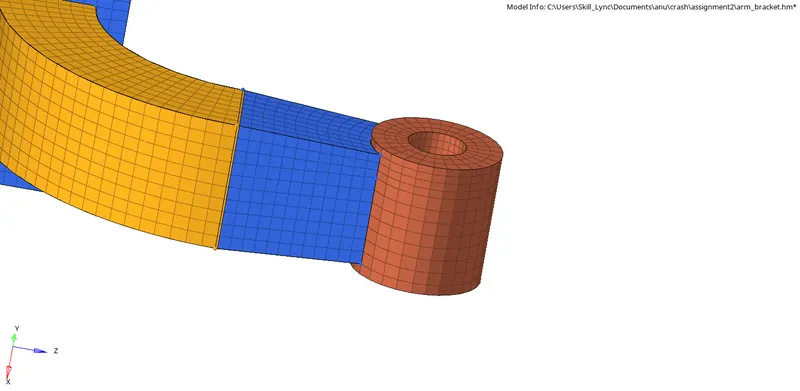
Hence the complete model was hexa meshed .