Assignment 1-2D Meshing Challenge
OBJECTIVES:
- Clean the geometry.
- Extract midsurface.
- Clean midsurface geometry.
- Ignore holes less than dia 5mm.
- Create 2D mesh with target length 5mm, min 3.5mm max 7mm.
- And assign proper thickness, by creating a generic property.
PROCEDURE:
- Given below are the three components on which we have to perform the midsurfacing and meshing operation.
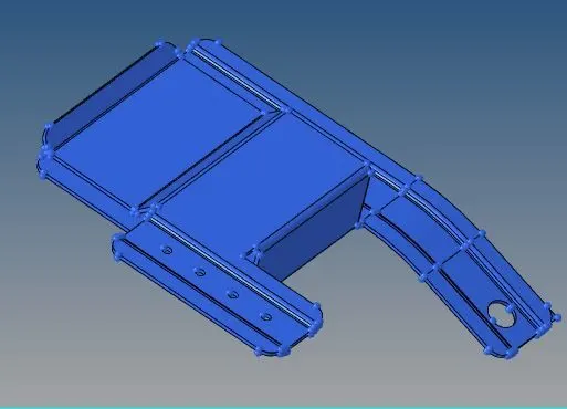
1. PLASTIC PART
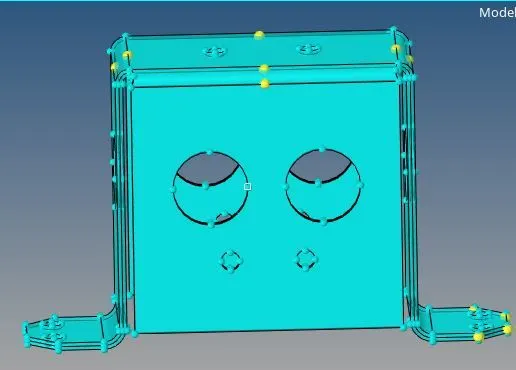
2.CLIP REPAIR
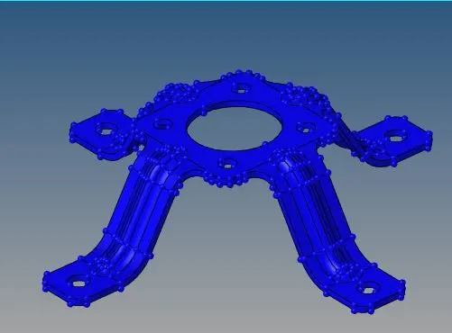
3. MOUNTING BRACKET
A. Geometry Cleanup
- Import the files to hypermesh under Radioss profile. And switch the coponent to toppo mode to check if there are any errors are present or not.
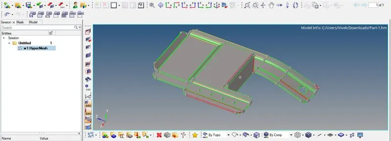
- So now we can see there are 3 types of cons present on the component. We have to eleminate the signle and tripple cons from it.
- For that we have to use some of the operation for cleaning the geometry of the coponent for that go to the GEOMETRY>QUICK EDIT
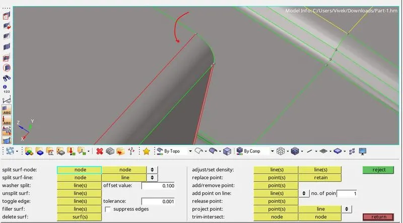
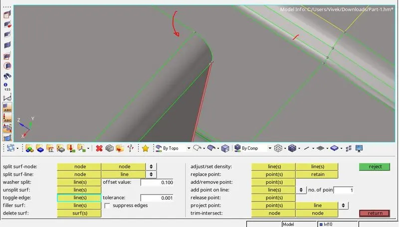
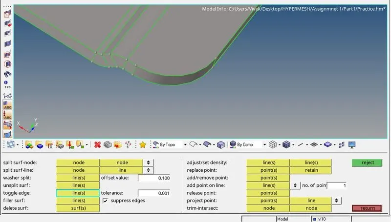
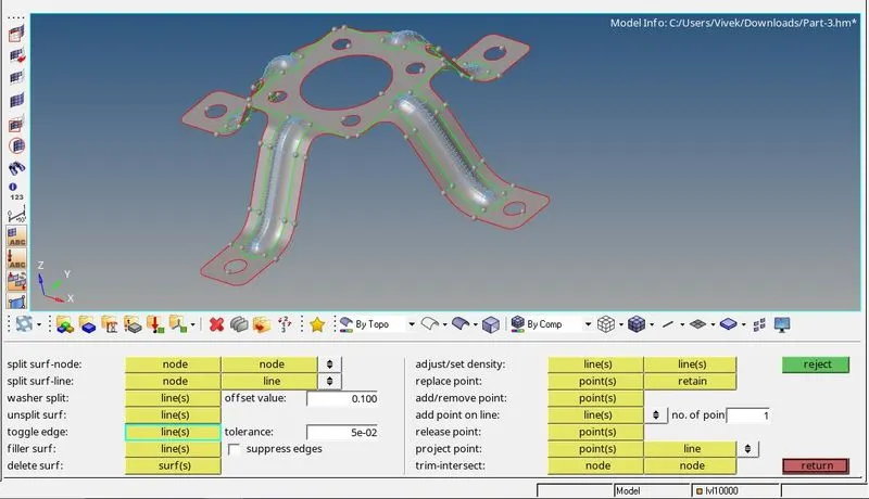
- Now as shown below there is a part which is not connected to the surface so for that we will use TOGGLE EDGE option and select the red line to connect the part. The performed operation is shown below:
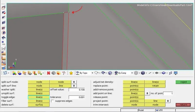
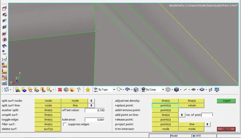
- Now the next as shown below there is gap between two cons so for that we wil use REPLACE POINT to joint the two points and make a same surface so first we have to chose the one point and other point on which we will overlap it so it is shown below:
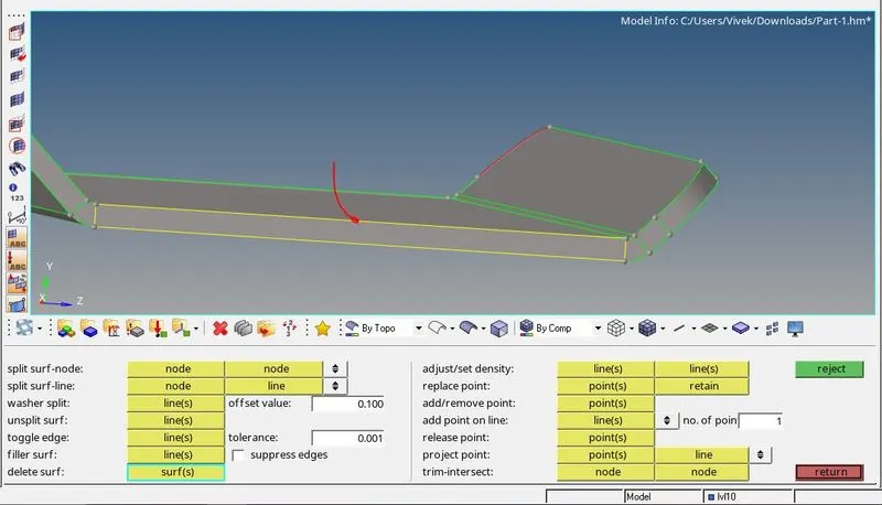
- Now given below is the face overlapping thats why it is shown with the yellow lines. The yellow line is known as tripple cons so to delete this surface we will use DELETE SURFACE and then select the surface which we want to delete. As shown below:
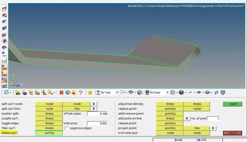
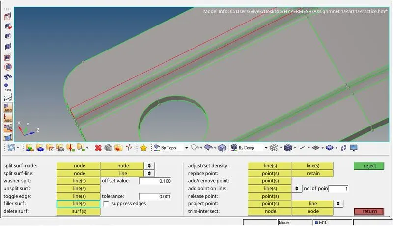
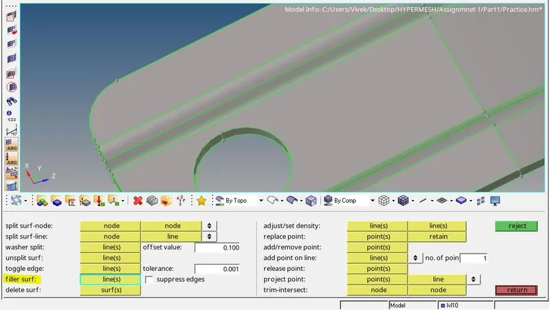
- Now given below you can see the surface is deleted so for to create a new surface there we will use FILLER SURF. option and after that select the line which we have to fill and it will create the surface as shown:
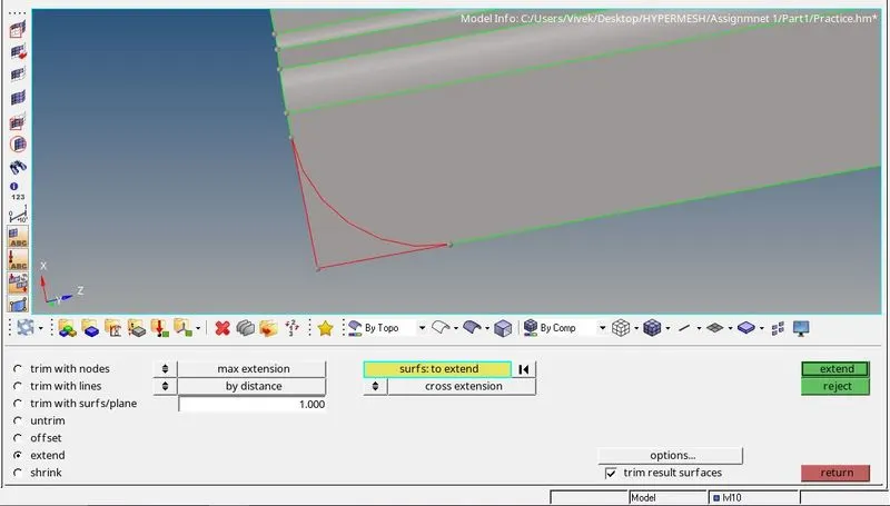
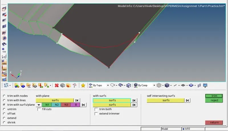
- Now shown below is extra surface we have to trim that extra part for that we will go to the GEOMETRY>SURFACE EDIT>TRIM WITH SURF then select the surf which you want to trim and then select the other perpendicular surface to that so we can trim only that part after that go to the quick edit and delete the unwanted part and perform toggle operation which is shown below:
- So the geometry cleanup is done. And the next is midsurfacing:
B. MIDSURFACING
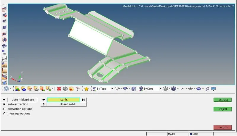
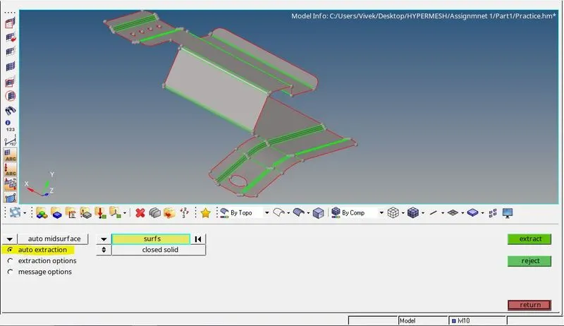
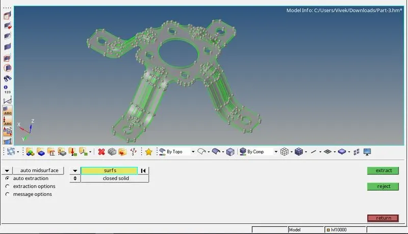
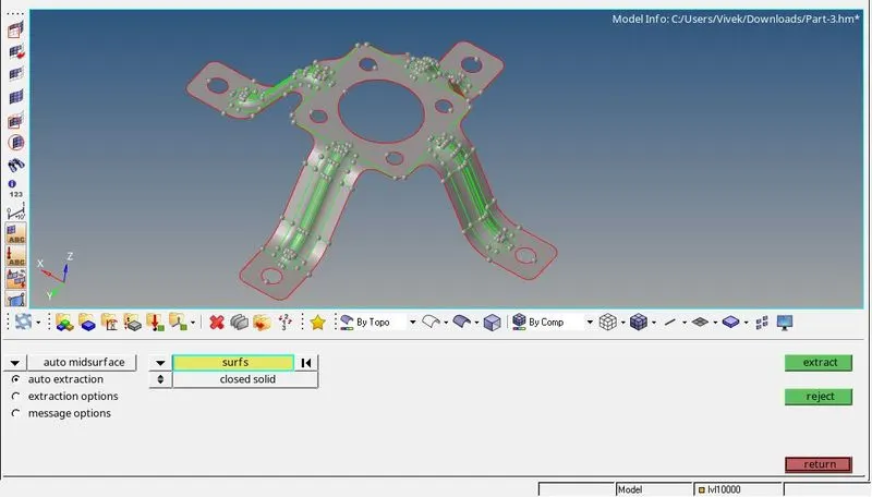
- Now for the midsurface go to the GEOMETRY>MIDSURFACE>AUTO EXTRACTION and then select SURF. The suface should completely close to perform the auto midsurfacing.
- After selecting the surface click on extract and midsurface will be formed.As shown:
1. PRACTICE PART
2.CLIP REPAIR
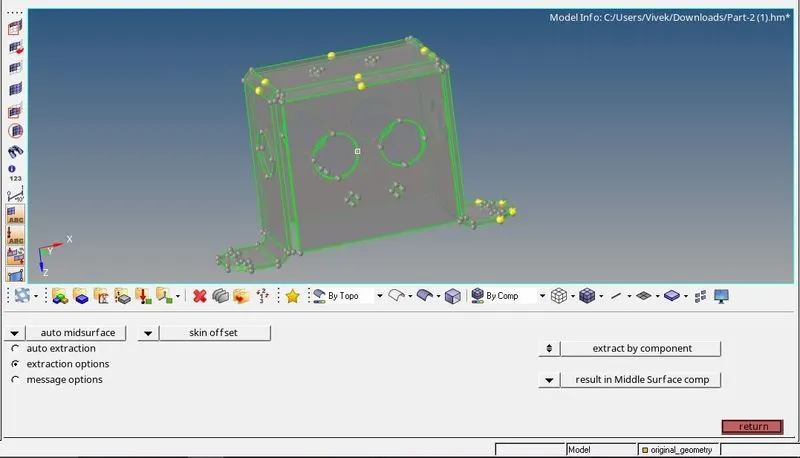
- For this will use GEOMETRY>MIDSURFACE>EXTRACTION OPTION after that select SKIN OFFSET then go to the AUTO EXTRACTION and then EXTRACT midsurface. As shown:
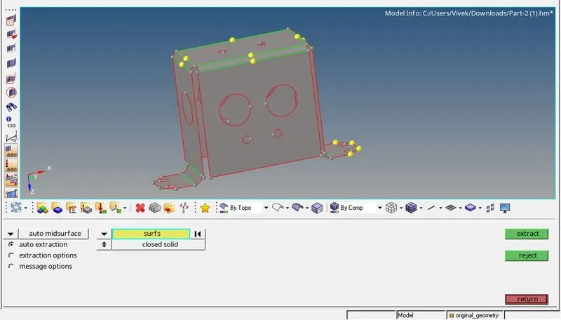
3.MOUTING BRACET
C. CLEAN MIDSURFACE GEOMETRY
- So after midsurfacing the component is ready for the meshing. But before that we need cleanup some geometry for getting good meshing.
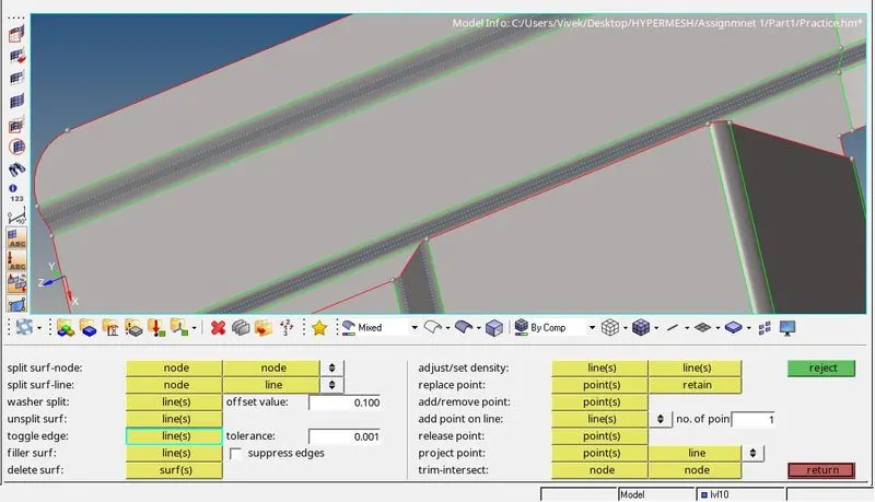
- So we are going to toggle the line which are going to fail for the minimum length criteria without distrubing the component.
- For that we will go to the GEOMETRY>QUICK EDIT>TOGGLE as shown below:
1. PRACTICE PART
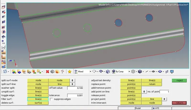
- Now for the good mesh flow we will avoid the holes whose diameter is less than 5 mm for that we will use GEOMETRY>QUICK EDIT>FILLER SURF. and fill those hole as shown:
2.CLIP REPAIR
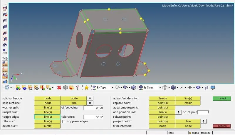
3.MOUTING BRACET
D. MESHING
- For meshing the criteria is given. Minimum length=3.5mm and Maximum lenght is=7mm and Tareget length =5mm
- To set the minimum and maximum length go to the TOOLS>CHECK ELEMS and add the values in the minimum and maximum length box. As shown:

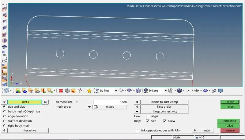
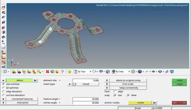
- Now for the mesh go tho the 2D>AUTOMESH
- For meshing target length should be 5mm as per given criteria.
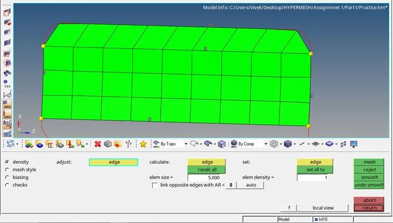
- So first select the surface which you have to mesh then click on mesh.
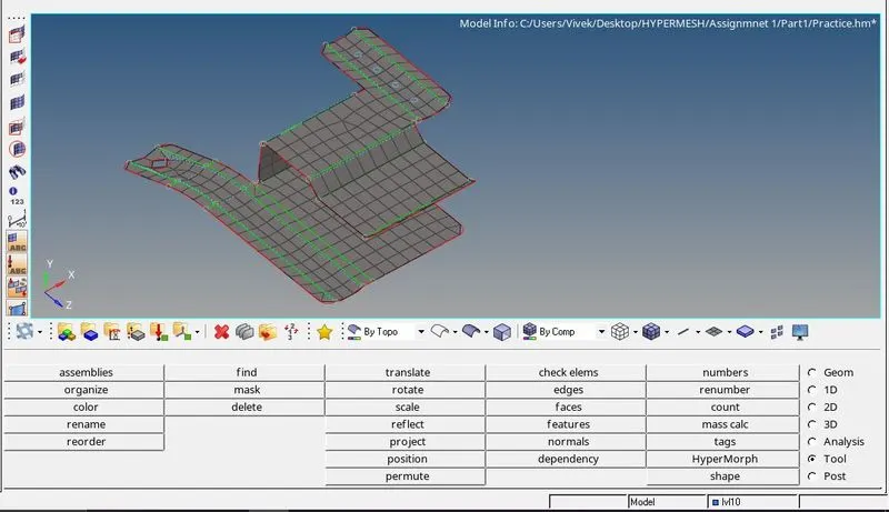
- The meshing of the component as shown below:
1. PRACTICE PART
2.CLIP REPAIR
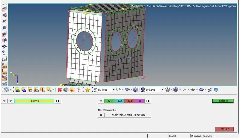
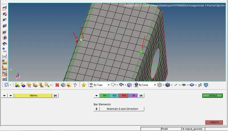
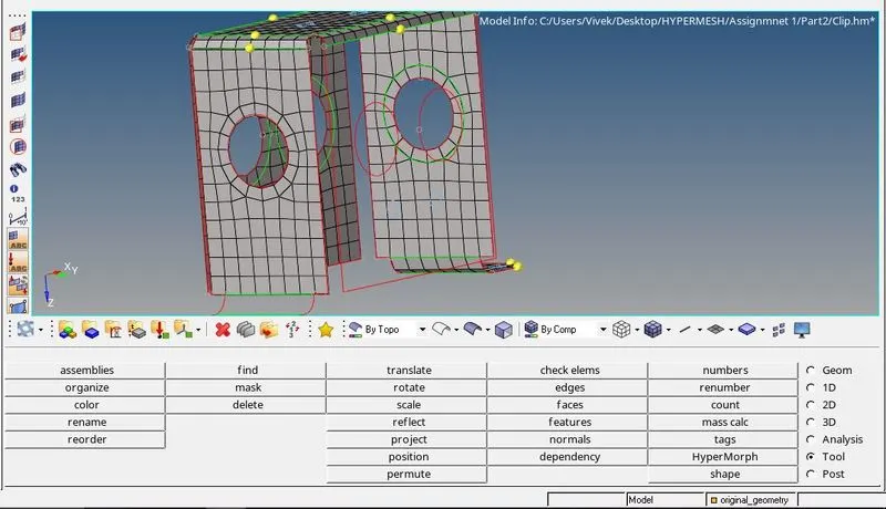
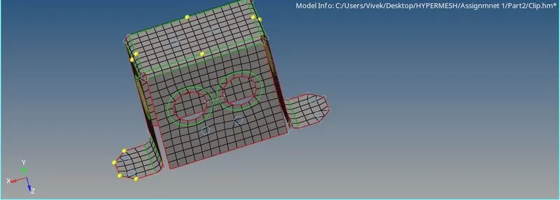
- Now in this part there are similar faces so we can mirror one meshed face on the other same surface.
- For that use TOOL>REFLECT and then select the ELEMS and slect the face which you wanna mirror, then select three nodes as reference and click on the reflect as shown below:
3.MOUTING BRACET
E. ASSIGNING THICKNESS
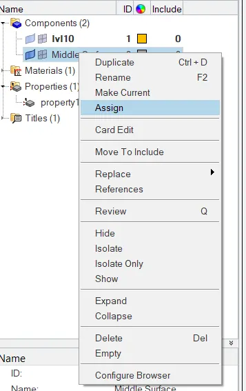
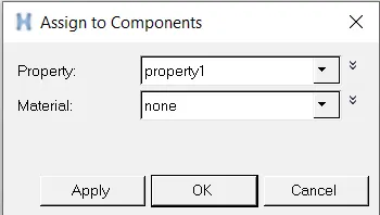
- To assign the property and thickness to mid surface, right click on the tab area and choose the create and the property.
- Now all the properies are entered in the property tab and the properties are assigned to respective midsurfaces.
- As shown below:
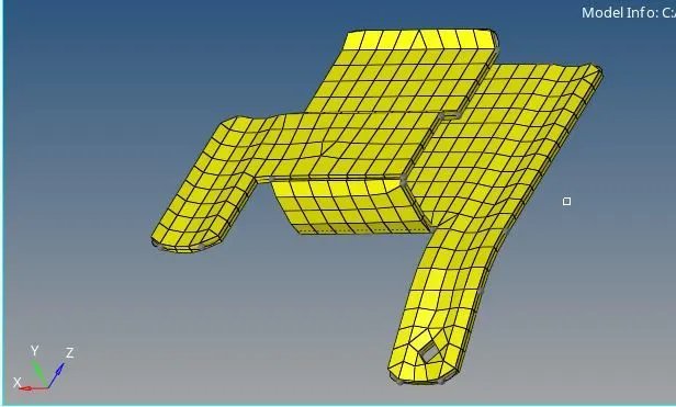
- The view the thickned mesh we will chose the 2D Detailed Element Representation from the TOOLBAR
- All the component are shown below:
1. PRACTICE PART
2.CLIP REPAIR
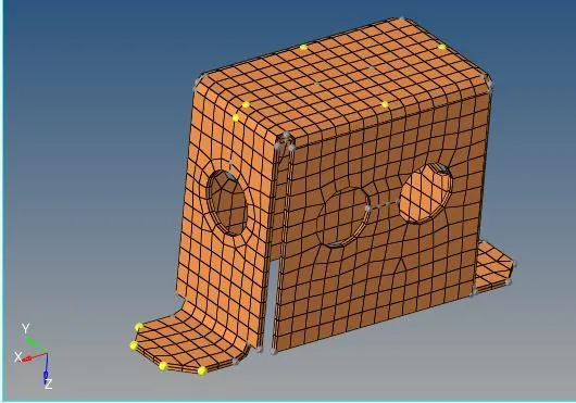
- 3.MOUTING BRACET
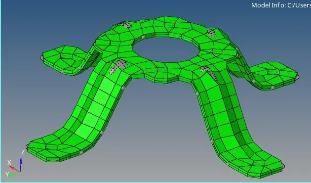
CONCLUSION:
- The geometry cleanup is done properly
- All the midsurfaces of the component are done with the proper meshing criteria.
- The proper thickness and material is assigned to all the component.