Assignment 1-2D Meshing Challenge
Aim :
- Perform geometry cleanup operation on given files and do this operations on them -
1) Clean the geometry;
2 ) Extract midsurface;
3 ) Clean the midsurface geometry;
4 ) Ignore the holes which are less than 5 mm in diameter;
5 ) Create 2D mesh with target element length of 5mm, and assign the thickness.
Procedure :
PART : 1 ]
1 ) Geometry Clean up :
- Import the model part 1.
- Check for any geometry distortions such as free edges, distorted surfaces, cracks etc.,
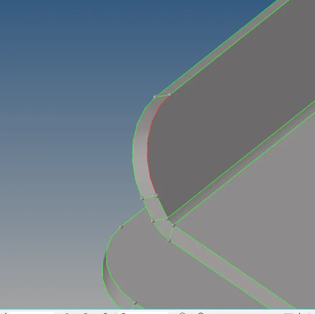
- In the above image we can see free edge because they are not connected.
- Just perfom toggle edge operation on the edge giving proper tolerane and both the edges will be connected together.
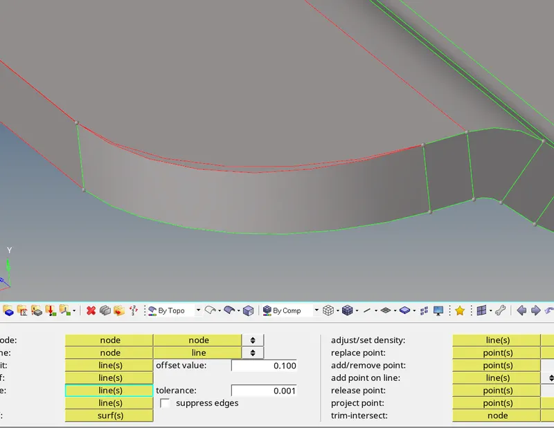
- In the above image there is abnormality which can explain free edge quite better.
- Free edges are represented in red colour, shared edges are in green colour, the edges which are shared by three edges are yellow in colour and the toggled or suppressed edges are blue in colour.
- To toggle this line, we should give the tolerance value to toggle command. This tolerance should be increased.
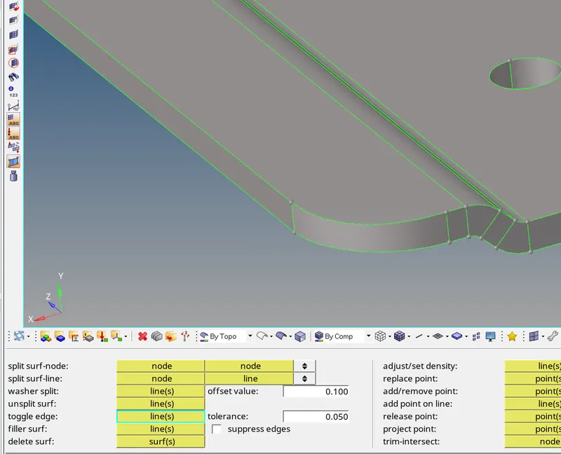
- We could see in above image, all free edges are toggled.
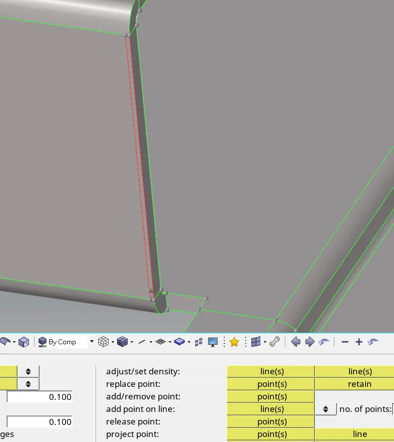
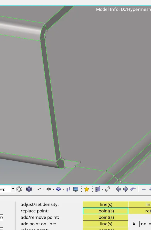
- In above image there is small strip of surface is missing.
- There are no of ways with which we can recreate the surface. One of which method we are using here is replace points tool.
- This tool extends the surface further to the next point. This is shown in below figure.
- Next diformation is over extended surface.
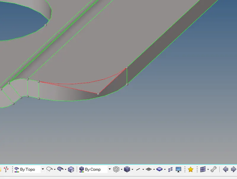
- Fillet operation is not done on this surface properly because of this, the face is moved forward.
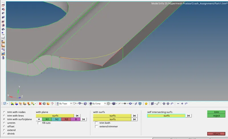
- In order to remove this type of abnormality, go to surface edit tool. In which there are options to trim the surface with another surface use any one of them. Which will trim the surface and now we can delete the extra surface which is in between yellow and red lines.
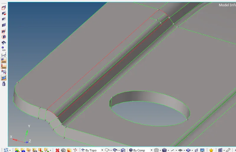
- Next abnormality we find was surface was missing. This could happen at the time of importing the geometry.
- Now, for recreating the surface go to surface geom panel -- > surface tool which provide many options for recreating that surface.
- Try all the options, whatever results are best go with them. In this case we got best results with filler/spline options.
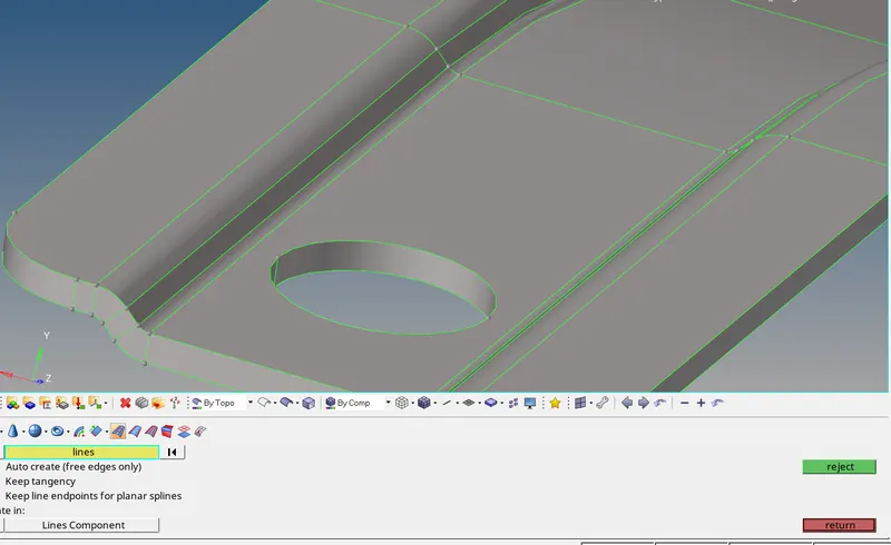
- There is one more type of distortion which could be seen in below image. There are yellow lines which represents ther must be three surface which are getting connected at single edge. But, we can see there are only two surfaces.
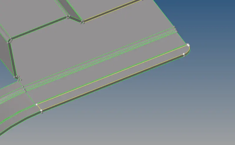
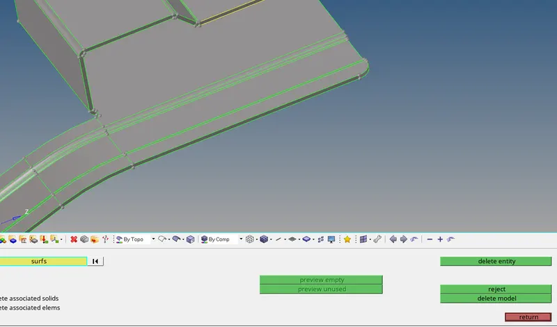
- This kind of issue arise due to duplicate surface. Delete the above surface which is connected with yellow lines. Once this duplicate surface gets deleted this issue will get resolved automatically.
MIDSURFACE EXTRACTION :
- Once the geometry is free from all the distortions go for mid surface extraction.
- Go to mid surface tool from geom panel which will offer different options for midsurface extraction.
- Select any one of the method of mid surface extraction.
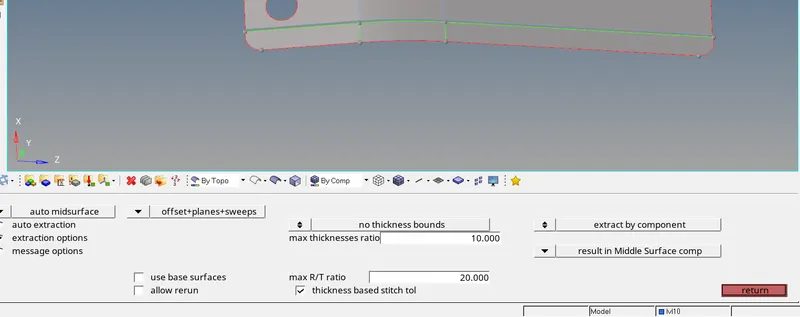
- I have selected this configuration for mid extraction.
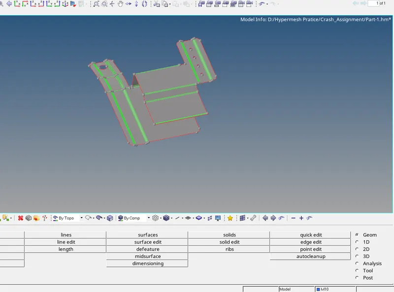
- This is the image of extracted mid surface.
MID SURFACE CLEAN UP AND MESHING :
- Check the mid surface for any deformation.
- We have to check the mid surface and do the modifications so that our minimum mesh size should not fail due the complex geometry.
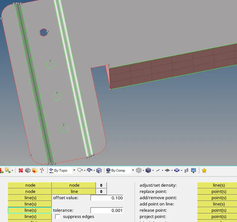
- The distance between the feature lines in less than 3.5 mm which is our minimum element size, thus our elements are definitely going to fail there. Hence, defeature the small fillets.
- Also, the holes are less than 5mm diameter. So, we can avoid modelling of this holes.
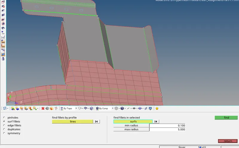
- Here, we have defeatured those holes.
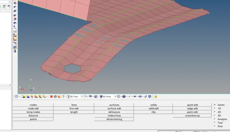
- Also, due to the constraint of small element size we cannot capture the geometry as it is. There are two cases -
1) Either we can capture the geometry fully and accept the failed elements or
2) Don't accept the failed elements and get a better mesh flow.
- Here we went for option 2.
- Wherever there is small fillet which will result in failed elements defeature them.
QUALITY CHECK :
- After meshing check the elements quality.
- Go to 2D panel --> qualityindex tool.
- There feed our quality criteria and check the failed elements.
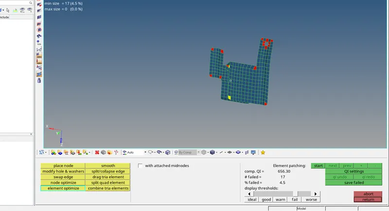
- In above image we can see that the quality parameters on top left side of page. Those elements which are failing for quality are shown in red or yellow colour as per their critical level.
- Many failed elements can be cleared with the help of options provided in quality index tool.(highlighted in yellow colour tab)
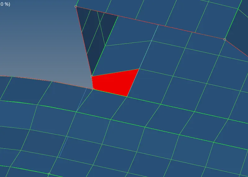
- This element is failing due to the feature itself. Distance between two points is more than 2mm,
- Our minimum element size is 3.5mm i.e., element will pass quality only when its minimum side is more than 3.5mm. If we do this then elements will move from feature lines too much which is not acceptable, thus accept the failed element.
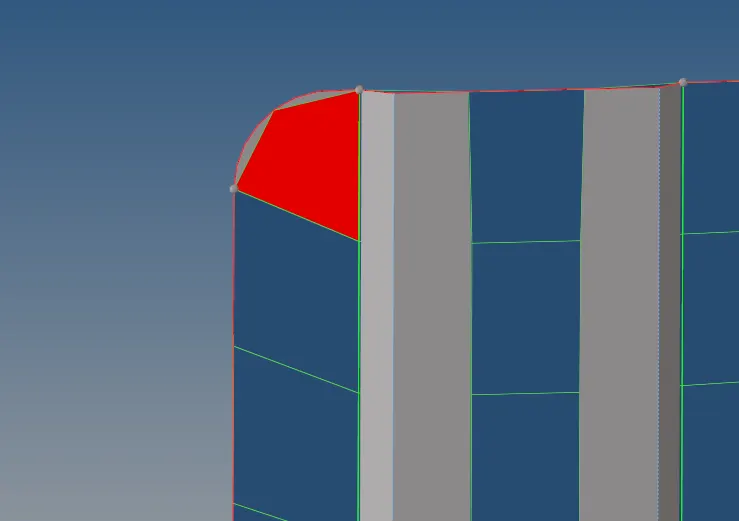
- This corner element is failing because of fillet. Thus deviating the element little bit from fillet and making element acceptable.
- To do this make use of align tool and element optimize tool from quality index tool.
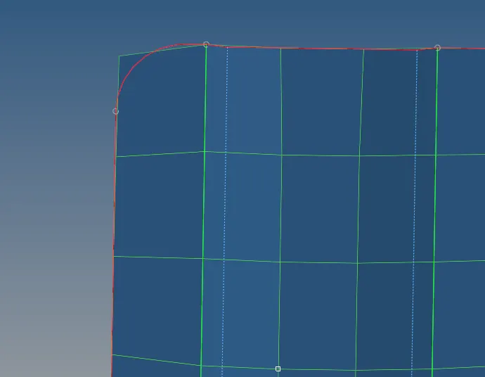
- In this way we prevented the element from failing with trying to capture the features as soon as possible.
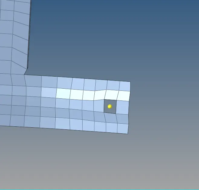
- Initially this hole was captured diagonally, thus was restricting the mesh flow.
- Hence, make the hole side parallel with any nearby edges by rotating the nodes.
- Use rotate tool from tools panel.
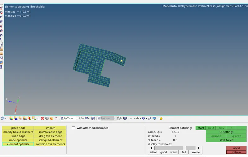
- Accepting the model with one failed element, because if we try to clear quality then the element will deflect from geometry a lot.
PART 2 :
GEOMETRY CLEANUP :
CAD IMAGE :
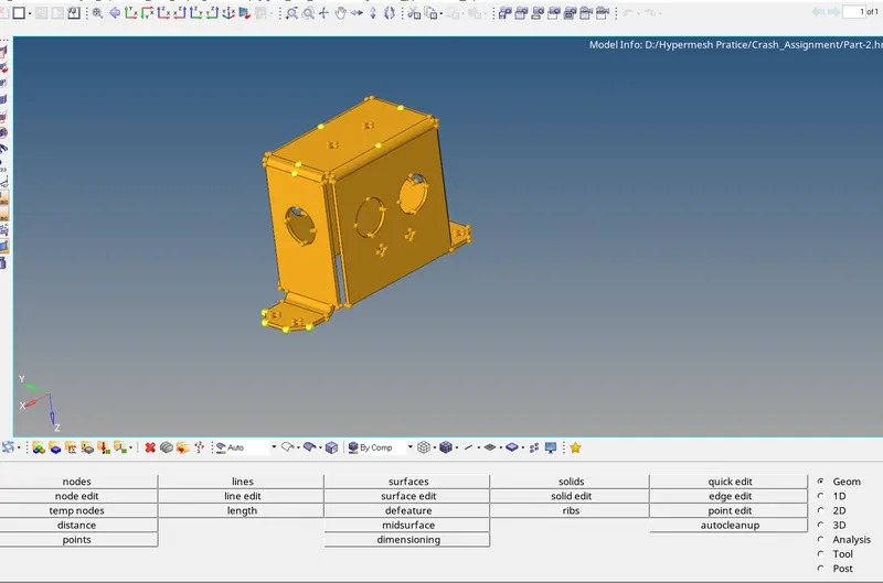
- View the model in Topo mode.
- This part is axi-symmetric.
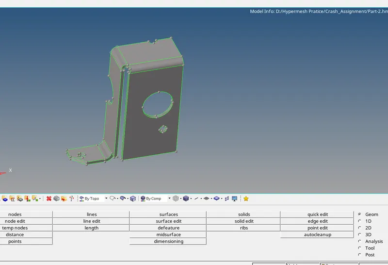
- Due to symmetrical part we will work only on this much portion and reflect the mesh.
- This geometry looks good for mid surface extraction.
- Thickness of this part is 2mm, this is a sheet metal part. Create property and material and assign the thickness to the mid surface.
MID SURFACE :
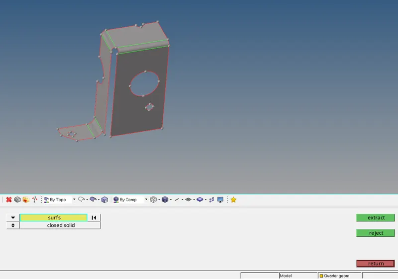
- This is the mid surface which we have extracted.
- Our minimum element size is 3.5 mm, check the surface accordingly.
- Holes less than 5mm thickness can be avoided for modelling. This holes are of 5mm thickness so we can fill them.
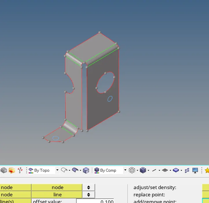
- Holes dia < 5mm are removed and surface is good for meshing.
MESHING :
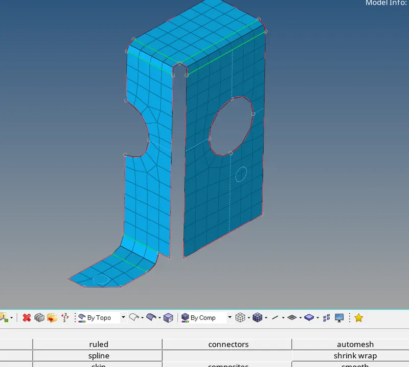
- Split the surface before meshing for a better mesh flow.
- Mesh the sections as per given element size. Remesh the elements for better mesh flow. Decide which is better pattern.
QUALITY PARAMETERS :
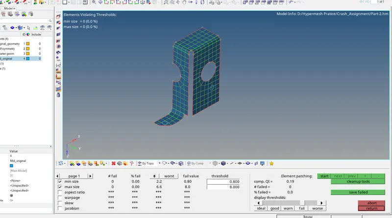
- Feed the quality criteria as per given parameters.
- Go to qualityindex tool from 2D panel, check for failed elements.
- There are no failed elements.
- Now, reflect the mesh elements.
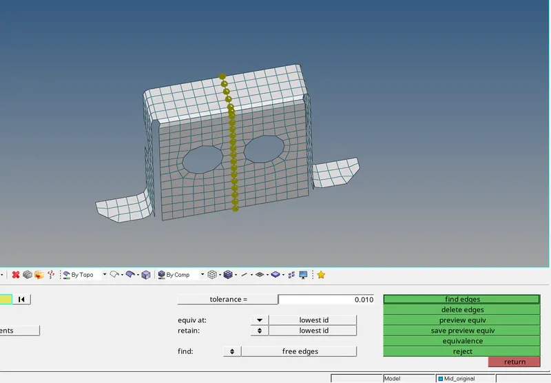
- After reflecting elements, check the elements for equivalence.
- Select elements give proper tolerance and say preview equivalence. If there is gap between two elements then software will show us brown colour nodes.
- Click on equivalence now. So that the elements will be joined.
- Perform the same operations on other for other half.
- Assign the properties and material to mesh.
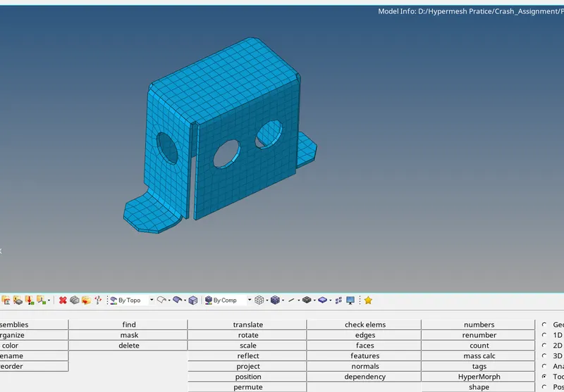
- This is final model image.
PART 3 :
CAD IMAGE :
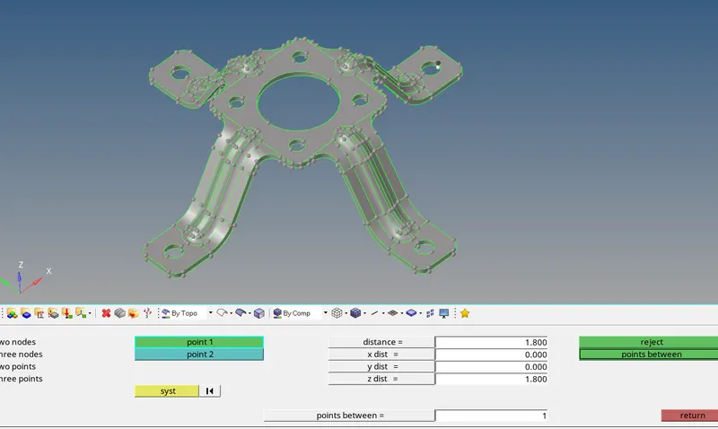
- Part thickness is 1.8mm make a property card having thickness as 1.8mm.
- This part is also symmetrical.
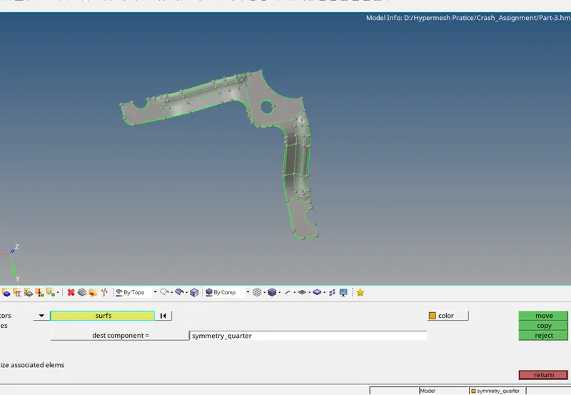
- We will work on only this much part due to symmetry of part.
GEOMETRY CHECK :
- Geometry of part is free from any distortions.
MIDSURFACE AND MESH :
- Extract the mid surface of the section.
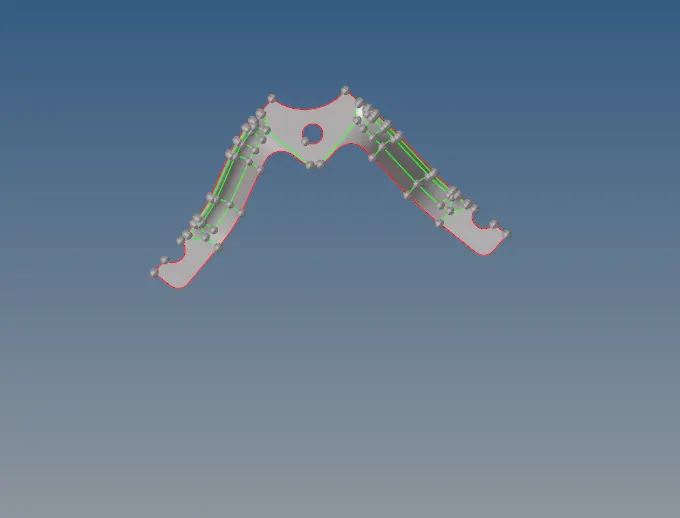
- This is the mid surface we got from automid surface.
- Toggle the feature lines for better mesh flow.
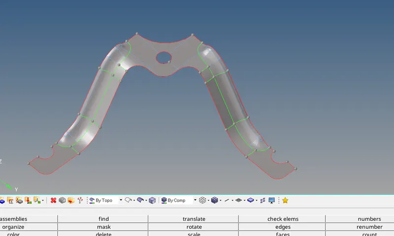
- For toggling the feature lines go to quick edit --> toggle edge.
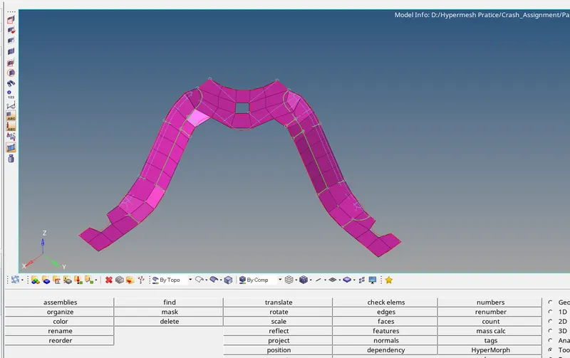
- Here we tried to capture as much as surface possible with minimum elements failing for quality.
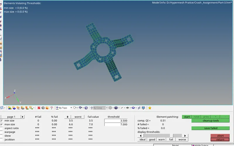
- Reflect the mesh twice in order to get complete mesh of the geometry.
- To reflect go to tools panel --> reflect. Select the elements--> decide the axis along which elements to be reflected and click on reflect.
- Before reflecting the elements duplicate the elements.
- Create material card and property card by right clicking on browser section and assign thickness in property card.
RESULTS :
- In this challenge, all the three parts had complex regions where capturing geometry along without any failed element was a big task.
- The minimum element size given was 3.5mm and many features were of length less than 3.5mm.
- This was the challenge to capture the geometry and preventing the elements from failing as well as maintaing good mesh flow.
- While meshing we kept in mind to balance all the aspects.
- Two models were axy-symmetric, thus divided the part along the axis and then processing it which saved huge amount of time while modeling. Which even made it possible to solve the model within given time.
CONCLUSION :
- In order to get a proper mesh flow and to capture the geometry while keeping in mind that no element should fail, we need to solve the model with trial and error method. We need to try modeling the part with all possible ways and to bring forward whatever is best.
- Priority is always given to feature capturing but we can not neglect quality of mesh as well.
- Thus, a thin line was maintained in between feature capturing and quality of mesh.