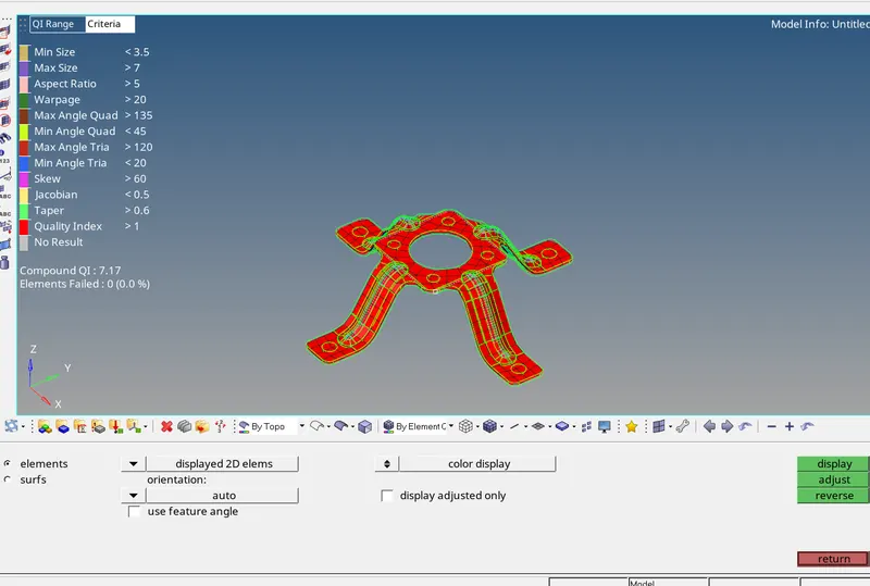
Assignment 1-2D Meshing Challenge
Objective :
- Performing the Manual Geometry Clean up on the given CAD Models .
- Extracting the Mid-Surface for each CAD model .
- Geometry Clean up of Mid-surface .
- Creating the 2D mesh with given Traget Element Size of 5 mm , so that it should not fail For minimun length of 3.5mm and maximum length of 7 mm .
- Checking the Mesh Quality Against the Quality Criteria provided
- Assigning the Proper thickness by creating the generic property .
CAD Model :
1 ] Model 1 :
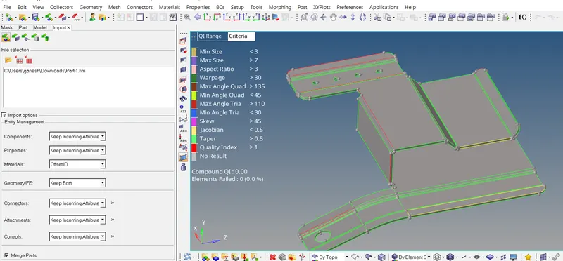
2 ] Model 2 :
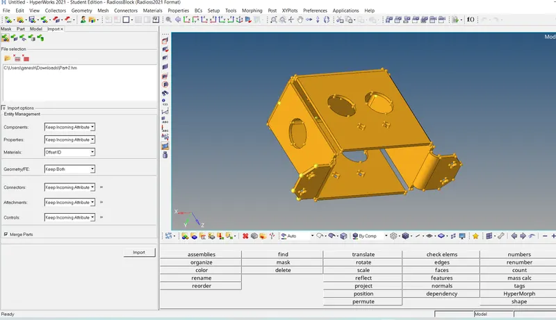
3 ] Model 3 :
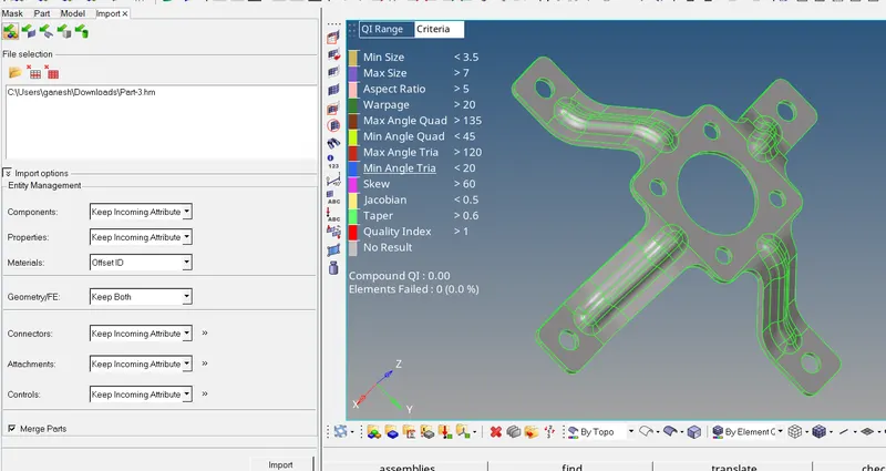
Model 1 ] :
Geometry Clean-up :
- Model Is Imported Using the Import Model Tool from manu bar .
- After that the Some disturbed geometry , which need to be taken care .
- In below Images the disturbed or messed geometry can be seen below as ,
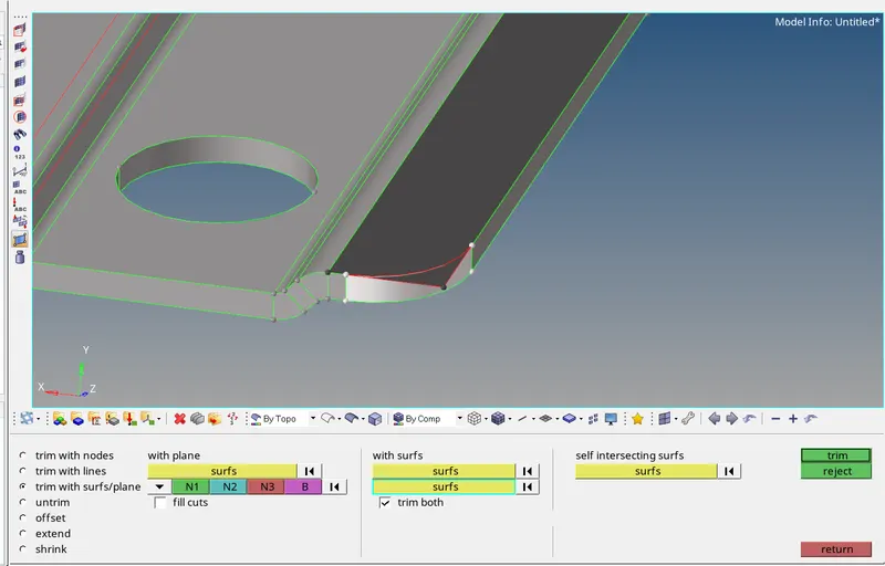
- Above Messed surface geometry is takled by triming the surface with another surface .
- Using the Trim with surface - Surface edit Tool bothe surfaces are trimmed
- Them unwanted surface is deleted .
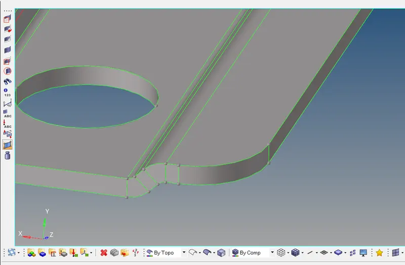
- In below Picture , We can see that the small surface is missing .
- This Surface is created by using the Rulled - Surface - Geom. Tool .
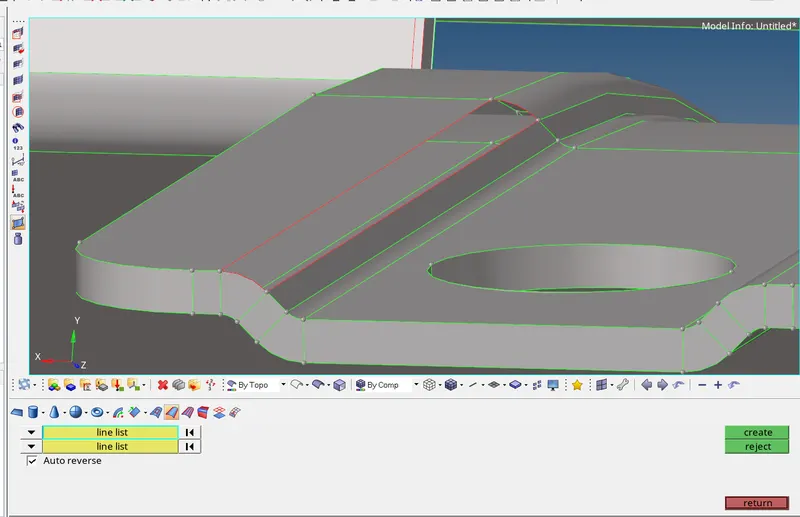
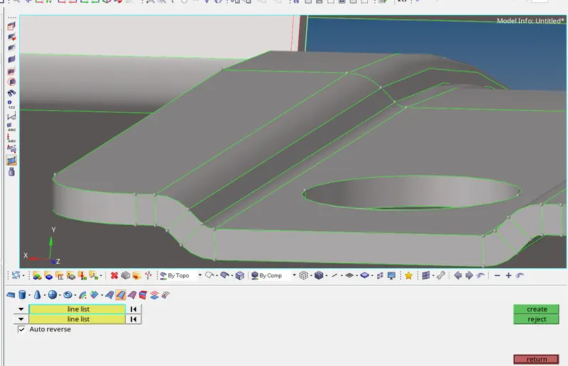
- There are some Duplicate surfaces created while importing the file which can be identified by the Yellow lines as ,
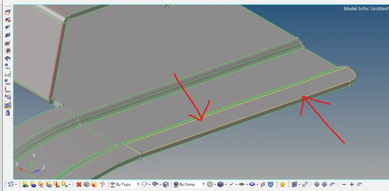
- Yellow lines indicates that , this line is connected to more that 2 surfaces , which here would not be possible .
- So this issue can be resolved just by deleting the upper/duplicate surface created , Using the Surface - Delete Tool , whic can be seen below as ,
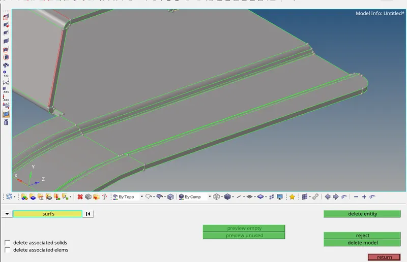
- Others Duplicate surfaces are also delted the same way .
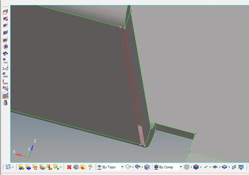
- In below image , there is missing surface .
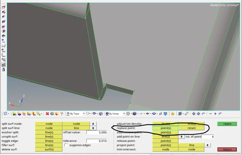
- This issue is resolved just replacing the points as seen below , using the Quick Edit Tool ,
- There are some surfaces which are connected properly to each other can be seen below .
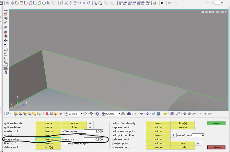
- This Surfaces are connected to each other by toggling the commen line between them , using the toggle line -Quick Edit Tool
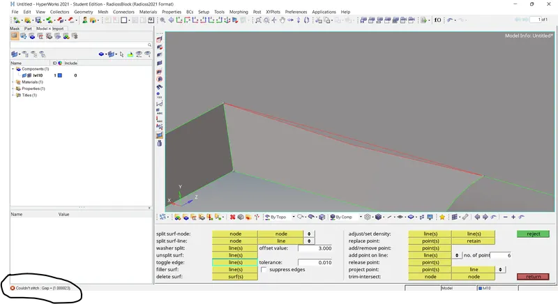
- But in below case the gap between them was sligthly more that the tolerence provided , which is further increase for safely toggling the lines .
Mid-Surface Extraction :
- After compliting the Geometry cleanup .
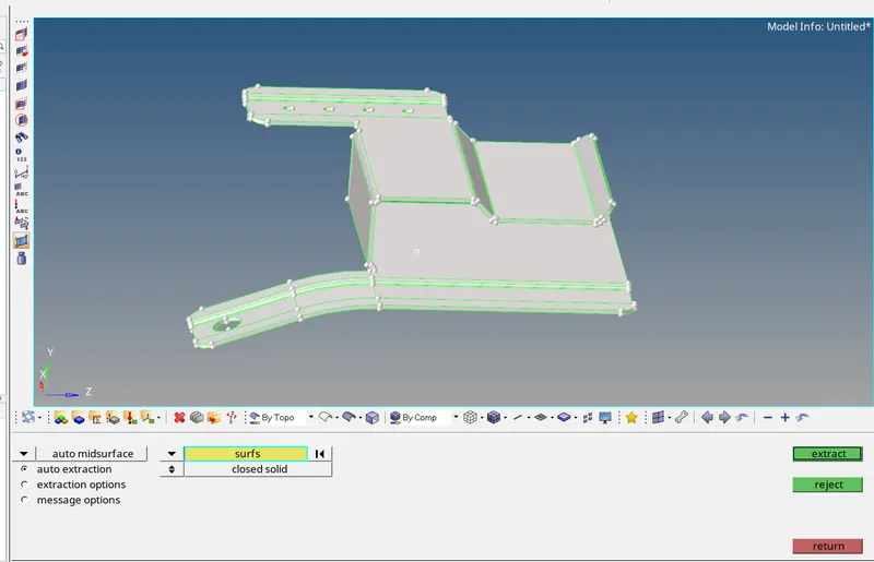
- Mid-surface is extracted of the whole model using the Mid-surface - Geom Tool as .
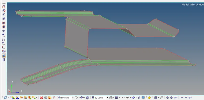
- Before meshing start , we have to do some geametry clean up of the midsurface , so that elements will not fail for some messy region .
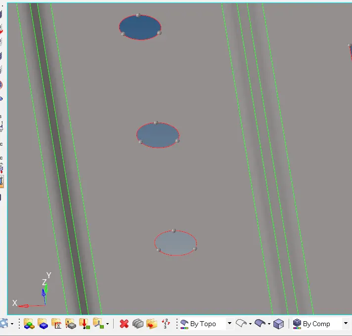
- The Holes whose diameter is less than 5 mm are removed , becuase the mesh elements near this hole would have fail for the Minimum length.
- This Holes are removed using the Unsplit - Quick Edit Tool .
- Removed holes can be seen below as ,
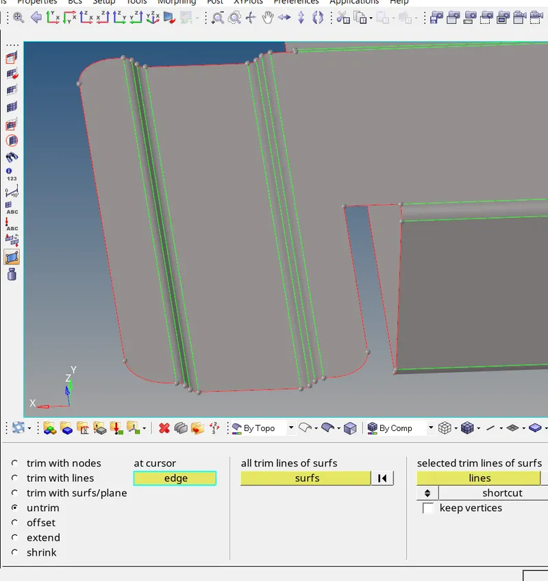
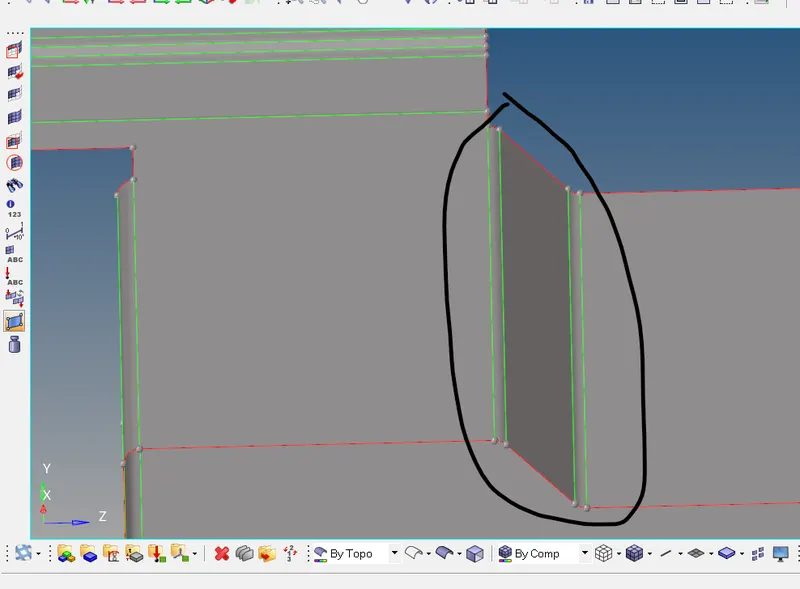
- Some surface filllets are also removed as , on fillet also elements would have failed for the minimuum length .
- Using the Surfaces -Defeature Tool , small fillets are removed as ,
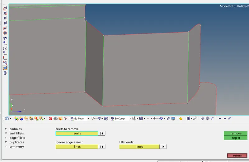
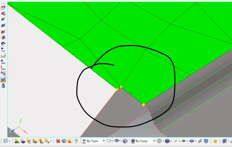
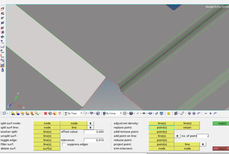
- using the Replace points - Quick Edit Tool , some Points are also replaced , so that the mesh will not be messy .
Meshing The Mid-surface :
- Surfaces are messed using the Automesh - 2D Tool or for some region other manual meshing tools are also used likes Ruled Tool , Drag Tool .
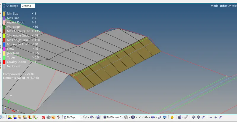
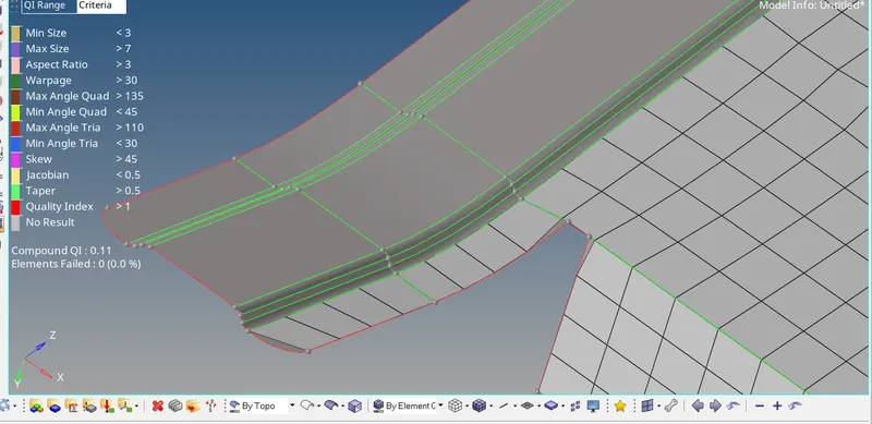
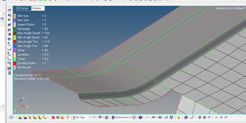
- The Regions where still elements were failing for Minimum length are can be seen below as ,
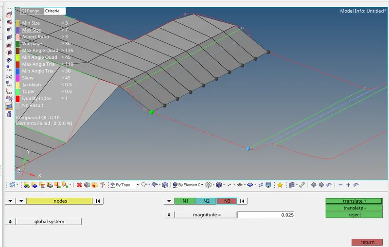
- This elements are Saved from failling for minimum length , just transffering the Nodes to the opposite side , can be seen in below image ,
- On Midsurface also some lines are toggled for avoiding the elements fail for minimum length .
- Then by creating the material and the property , Thickness is assigned accourding to Components Thickness .
FInal Meshed Model :
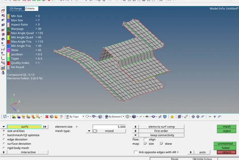
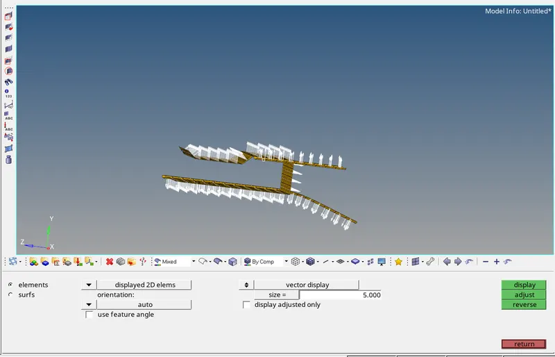
- The final Mesh should be checked for Normals .
- The can be checked using the Normals - Tool
- The Normal check for meshing created ,
Model 2 ] :
Geometry Cleanup :
- The Model is imported using the import Model File Tool from the manu bar as ,
- On this Model , there are no any geometry cleanup is needed as there is no any surface messed or lines to toggle .
MidSurface Extraction :
- Midsurface is extracted using the Midsurface Tool - 2D tool as ,
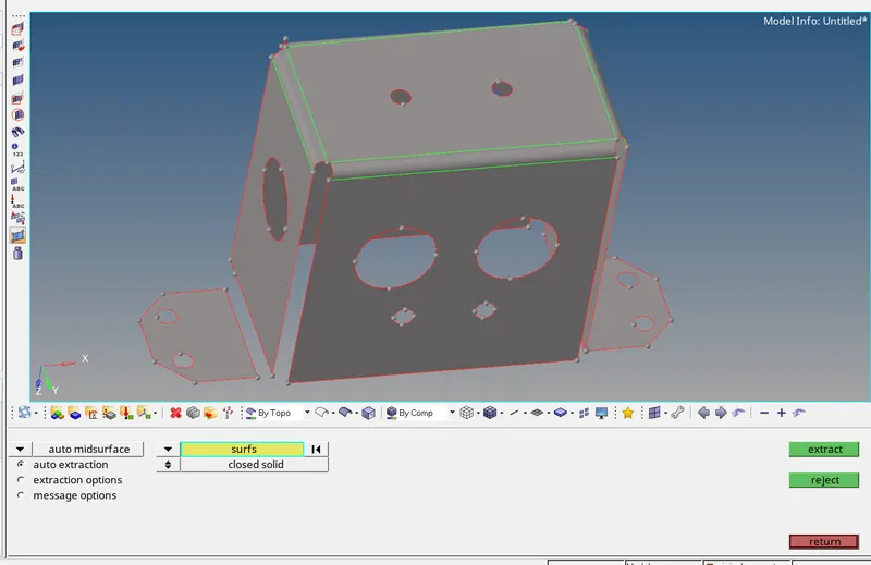
- But in above image we can see that the Auto midsurface tool has not extracted the midsurface of all the surfaces.
- This missing midsurface is then Extracted manually for both side , using the offset - Surface Edits - Geom. Tool as ,
- lower surface is offseted to tha half distance of the thickness of the CAD model .
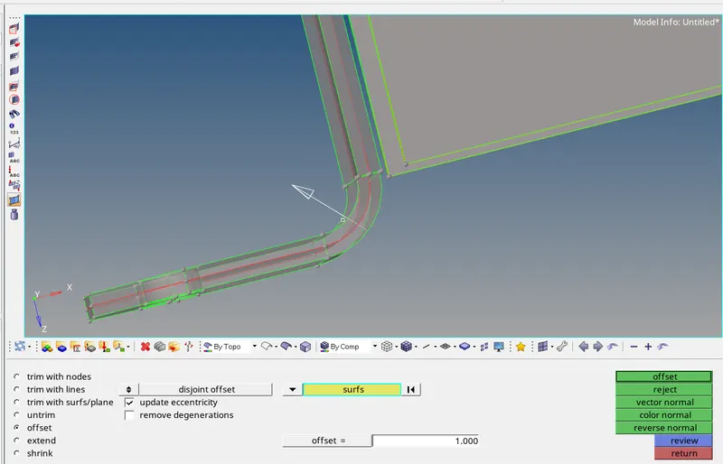
- The holes which has the diameter less than the 5 mm , are removed using the unsplit surface - quick Edit Tool .
Meshing :
- The Mesh is created using the Automesh - 2D tool as ,
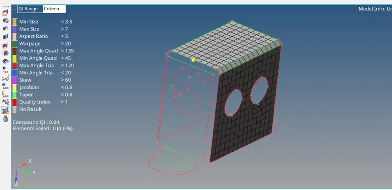
- Initially one side is meshed .
- This elements arethen reflected to the other surface as this surface are symmetrical about middle axis .
- Then by creating the material and the property , Thickness is assigned accourding to Components Thickness .
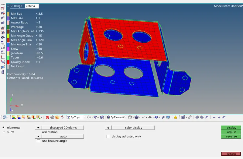
Final Meshed Model :
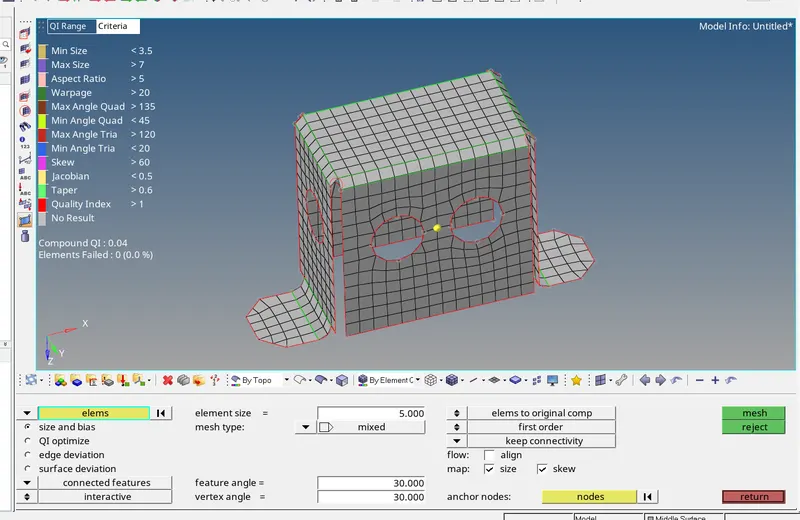
- The final Mesh should be checked for Normals .
- The can be checked using the Normals - Tool
- The Normal check for meshing created ,
Model 3 ] :
Geometry Cleanup :
- The Model is imported using the import Model File Tool from the manu bar as ,
- Here also there is no need of geometry clean up , as there is nothing which could be cleaned up .
MIdsurface Extraction :
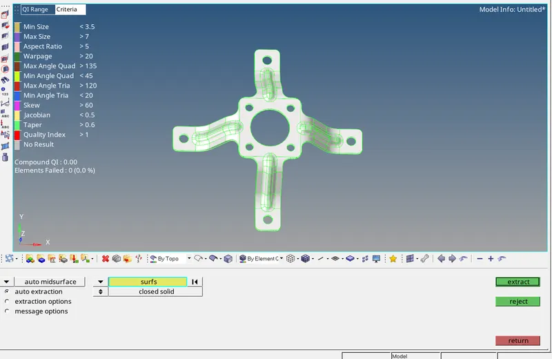
- Midsurface is extracted using the Midsurface Tool - 2D tool as ,
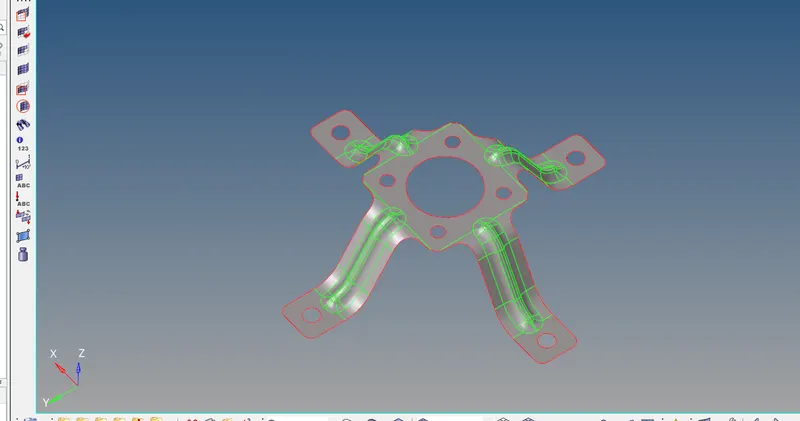
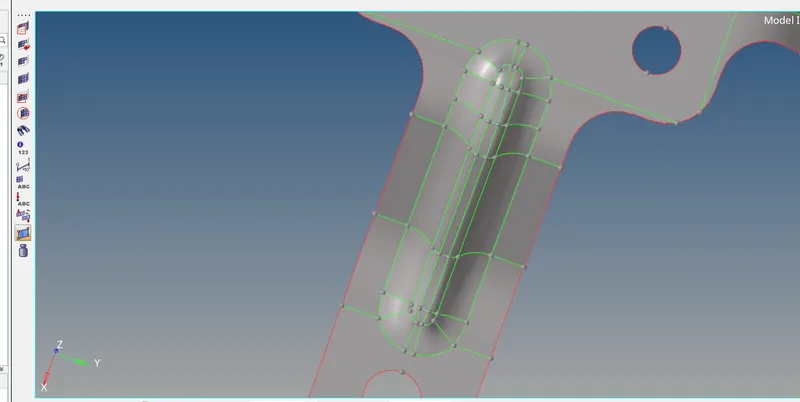
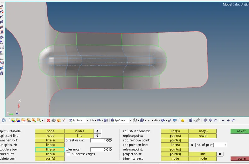
- Here in below image we can see there are lots of topological lines , which will try to fail the elements for minimum length .
- This lines are toggled using the Toggle lines - Quick edit Tool as ,
Meshing :
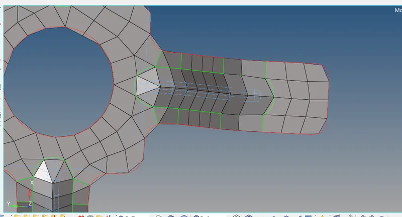
- The Mesh is created using the Automesh - 2D tool as ,
- Initially only one rib is meshed and then this elements are rotated through the 90 degree , using the Rotate Tool .
- Then by creating the material and the property , Thickness is assigned accourding to Components Thickness .
Final Meshed Model :
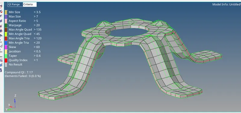
- The final Mesh should be checked for Normals .
- The can be checked using the Normals - Tool
- The Normal check for meshing created ,