Assignment 1-2D Meshing Challenge
AIM: To create a refined geometry and obtain a 2D mesh from the mid surface with a 5mm element dimension.
Procedure
1. File Typer Definition: The given model was opened in Hypermesh where file type was defined as RADIOSS.
2. Given Geometry:
From the given model, Red marked edges were prominent in the (a) Practice model only, signifying the need to clean up the geometry.
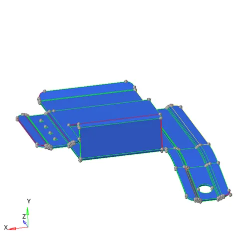
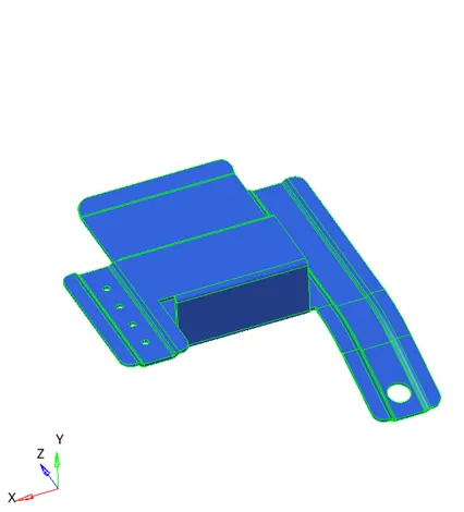
Before and After Geometry Clean up
(a) Practice Model
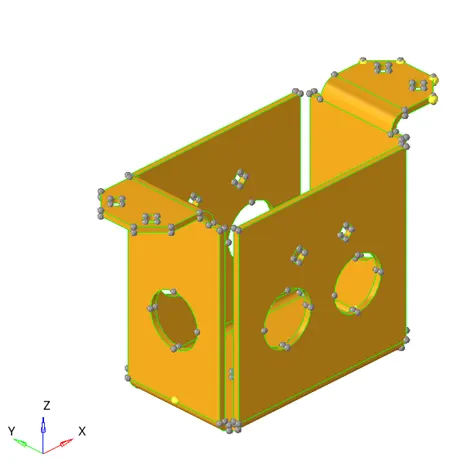
(b) Clip Repair
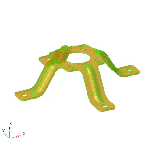
(c)Mounting Bracket
3. Mid-Surface Generation and Simplification
As it was defined that in the given model, any load within 5mm diameter can be ignored for meshing. Thus, in the given models, the mid surface geometry was modified accordingly.
The mid surface option under the Geometry card was used to generate the mid surfaces of the given parts.
Midsurface modifications:
- Quick edit card was extensively utilised to carry out mid surface simplification process.
- Surface fillets to remove the holes accompanied by toggling the lines were used.
- washer split was utilised to create a mesh around the holes.
4. Mid-Surface Meshing
- After simplification, the mid surface was meshed using appropriate options. 2D mixed mesh was utilised using the Automesh option under the 2D card.
- A mesh size of 5mm(given) was defined.
- Firstly, the surface mesh was utilised to mesh the mid surface.
- Once the mesh was obtained, then elemental mesh was utilised to mesh the deformed areas according to the user preference.
- The point replace option was preferred in case two points existed in close proximity.
- Finally, after the desired mesh was obtained, the obtained elements were transferred to the given model using Shift+F11 shortcut key to move the elements or nodes to a particular collector.
5. Mesh Quality Determination
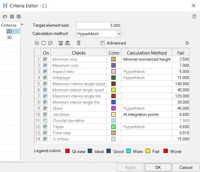
- Minimum mesh of 3.5mm and maximum mesh of 7mm was given as limit. these values were defined in the quality check dialogue box and the plots were obtained to determine the efficiency of the meshed geometry. Other essential parameters like Skew, jacobian, Warpage and Aspect Ratio options were left as default as the paraments were not the scope of this study.
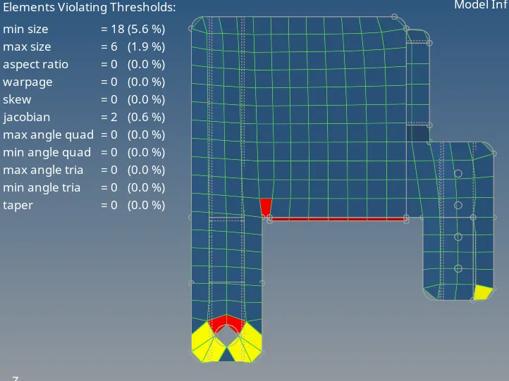
(a) Practice Model Mesh Quality: fine elements were defined in the boundary to capture the hole and edge curve of the given model thus leading to 5.6% of the elements being below the limit of 3.5mm element size.
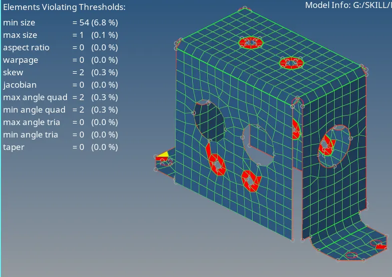
(b) Clip Repair Mesh Quality: Similar effect was determined, where the elements falling in the washer split region were below the given threshold limit even with minimum element number definitions. Apart from the washer split elements, the complete geometry reminds below the defined limit.
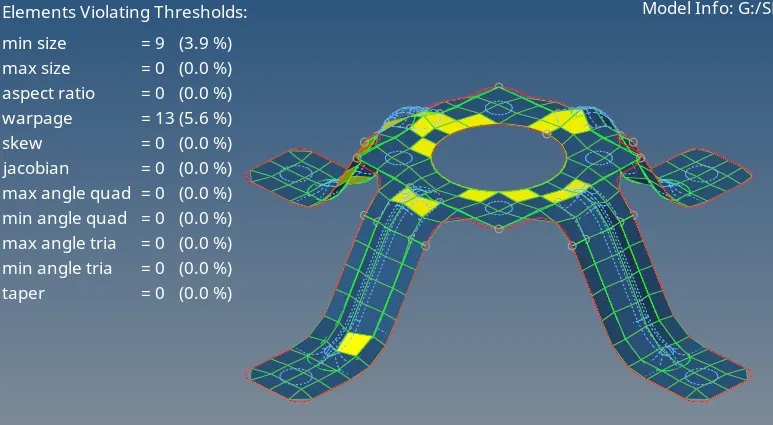
(c)Mounting Bracket Mesh Quality: about 3.9% of the elements were found to be close to the given threshold limit which is in the acceptable range.
6. Thickness Definition
Finally, using the properties option, a thickness of 2mm was defined for all the parts and a 2D detailed representation option was utilised to check the assigned thickness to the material.

(a) Practice Model
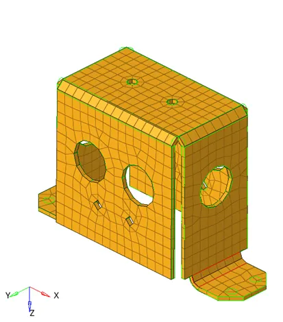
(b) Clip Repair
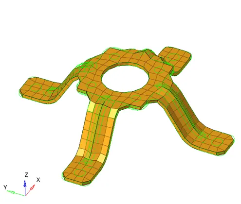
(c)Mounting Bracket
7. Conclusion
- All the three given models were cleaned and the mid surface was generated.
- In the practice model, the geometric cleaning option was used effectively.
- Quality check was carried out after meshing of the mid surface and it was observed that structural modifications were needed to obtain an equivalent mesh in the given geometry.
- Finally, the mid surface meshed elements were transferred to the given model collector and a thickness of 2mm was defined.