Assignment 1
AIM:
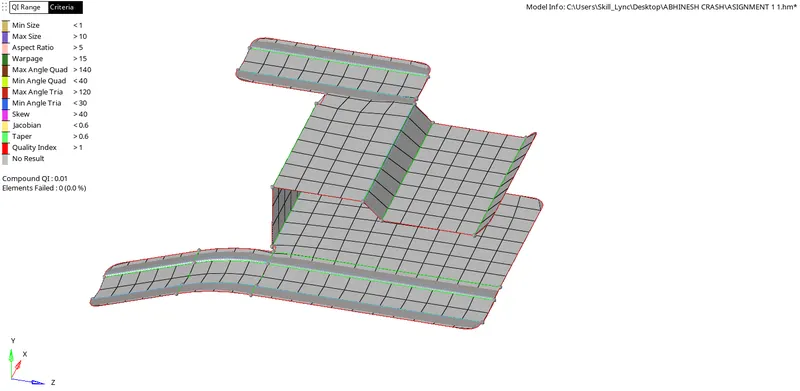
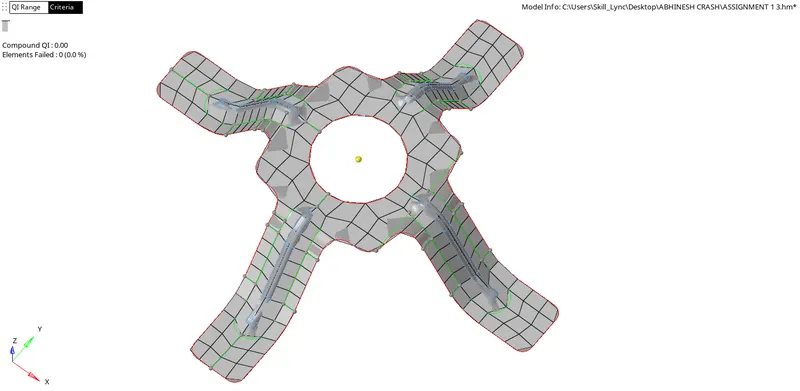
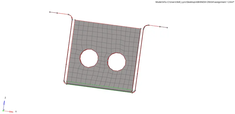
To Clean the geometry, Extract midsurfac, Clean midsurface geometry , mesh the component and assign proper thickness, by creating a generic property. with target length 5mm, min 3.5mm max 7mm.
GIVEN MODELS:
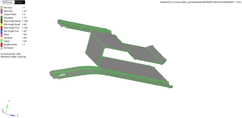
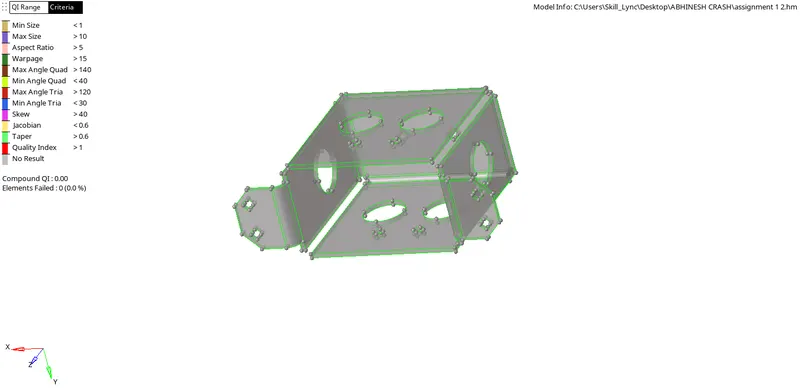
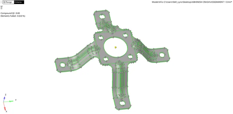
PROCEDURE:
STEP 1: Opening the File:
- The File given is a ‘.hm’ File. It can be opened directly by following the steps.
- In the Main Bar, Select File >> Click Open >> Click Model>> Select the File to open >> Click Open.
- The file is opened. To view the Model (if the Screen is empty), Click ‘f’ on the keyboard to fit the model on the screen.
STEP 2: EXTRACTING MID SURFACE:
- As the components are of uniform thickness we can use auto mid surface by using skin offset option.
- For Auto midsurface go to Geometry>Midsurface
- Go to extraction options then choose skin offset for better offset
- Then go back to auto extraction, Select the parent surface body which we want to create auto mid surface. Duplicate it. Then click on extract.
- After sometime we get the auto midsurface
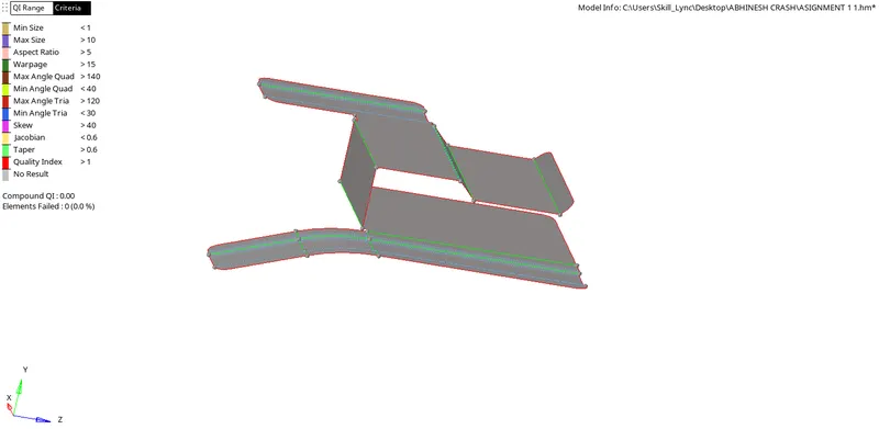
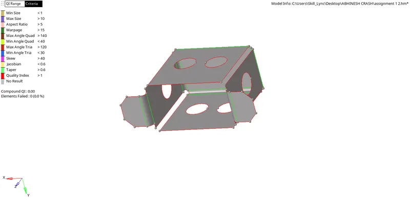
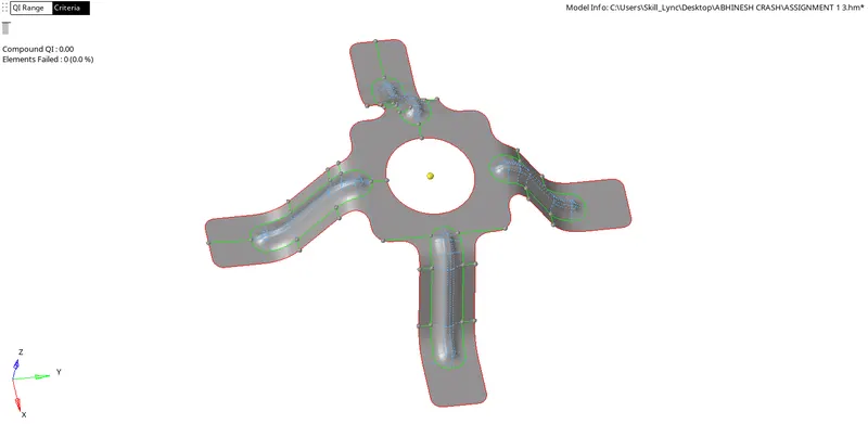
STEP 3 : GEOMETRY CLEANUP:
- After importing the midsurface we can Check for deformation.
- The parent have deformations like,
- It was having missing surafces which can be fixed by using filler surface tool in quick edit
- And some lines where shown in yellow lines which we can understand that there is an extra surface.
- Which we can remove by selecting the surface and deleting using delete surface option in quick edit.
- Also there was holes less than diametre 5 mm .
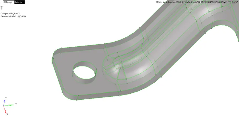
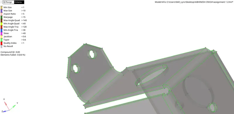
- This is removed by using unsplit surface tool in quick edit panel.
STEP 4: MESHING:
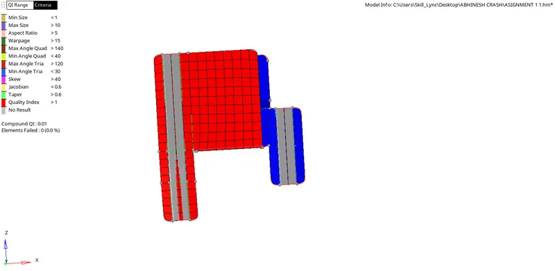
- After setting up the Quality criteria of minimum and maximum length we can start the meshing process.
- 2D> Automesh.
- After clicking on the surface box Select the surfaces needed to be meshed.
- Give element size as 5 as in the question
- Give the mesh type as Mixed.
- Elements to surface component is choosen to add the mesh to the surface component
- Keep connectivity is given to keep the mesh connectivity
- Check the Align and size to get a good mesh flow.
- Click on mesh.
- We can change the surface to elements and select the elements we want to remesh and click on Mesh to remesh the elements
- The mesh we get will have a huge number of trias, fixed trias and rotational quads. also the mesh flow wont be in a good pattern.
- Inorder to make it a good mesh. We will reduce the number of trias ( removing the unwanted trias)
- This can be achived be going to 2D> Quality Index> Cleanup tools.
- We can remove trias and get good mesh flow by using the cleanup tools
STEP 5: Checking the Normals and Free Edges
A. To check Normals
- To check the Normals go to Tool > Normals
- Choose elements
- Select displayed 2d elements for selecting the whole elemets
- Color display inorder for the color representation.
- Click on Display.
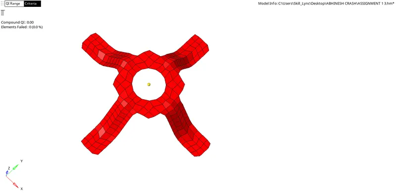
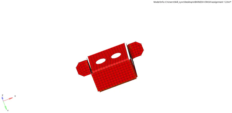
- Then we can see the whole model in Blues and reds. If the whole positive side is in one color and the negative side is in one color. Then it is ok.
- If one side is having both colors then we need to change its normals.
- By clicking on adjest almost all of it will be corrected.
- But if not we need to change that by Changeing the Displayed 2D elements to Elements and select the elements which we want to change.
- Then click on reverse. to change the normals.
B. To check Free Edges
- For checking normal we need to go to Tool> Edges
- Choose Elements> the select the whole elements.
- Click on Find edges.
- Now Hide other parts and Make edges mesh only visible.
- Now check if there is red line on any area which is not a boundary.
STEP 6: Assigning thickness.
- To make property. Right click on Model view area > Create> Property.
- Rename the property with the thickness value.
- Also set the thickness of the property. By clicking on property we can see its details below.
- In that we can see a T which represents the thickness give the thickness value . Click on enter.
- To Apply the property to the Components. Right click on component
- Select assign. Choose the property of the component from the pop up dialogue box
- Click on Apply. Click on Ok.
- To see the mesh in 3D. Choose the 2D detailed element representsation.
FINAL MODEL:
RESULT:
Finished the Mid surfacing and Meshing of the componentS with Zero fail of quality criteria . Also checked the normal and free edge and applied the thickness to the components.