Week 4- Challenge
OBJECTIVE:
To creat 1D elements on the following component with given cross-section and DOF.
CAD MODEL:
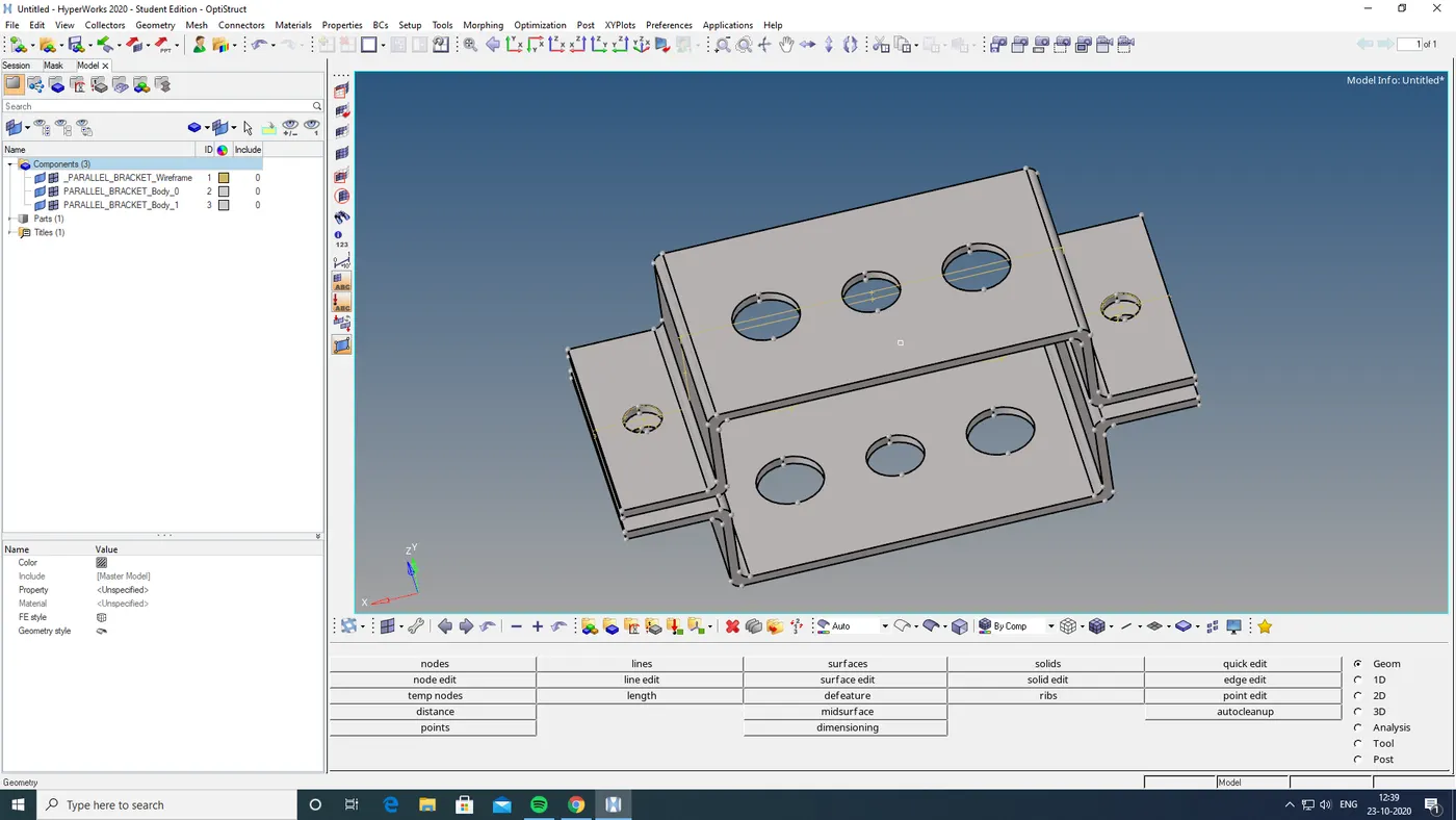
PROCEDURE:
- First i import the cad model
- then i applied points on the entire model
- then i converted those model to a wireframe model
- to create midsurface go geometry and go and select the componeents to get mid surfase and extract.
- then we go to component option and add a components inorded not to get a combined surface or ideal .
- by adding a component we next find the midsurface of down bracket.
- then we move the midsurface created to the created compunds using organise option in tool option
- by selecting the surface to be moved and selct move option
- and then it will change to the colour we given to the created compound
- then we select the matterial on the topleft corner option
- this will show the matterial details in down left cornerand defined
- then we should assign the propertyto the matterialand name it
- then made properties for all componet need to be specified
- select the thicknessfrom down left corner and also selct properties and card image as optstruct.
- and also select the matterial going to use
- same to do with other component also
- then we shound go 2D to automesh and select the meshtype as mixed
- before which we want to give washersplit to the holesfrom quick edit washer split
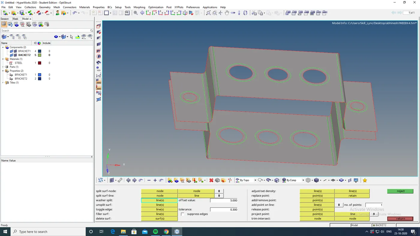
- and then we provide the offset value
- then we go to 2D and go to automesh
- then selct the surface and select displayed surface
- and give it as mixed and mesh it
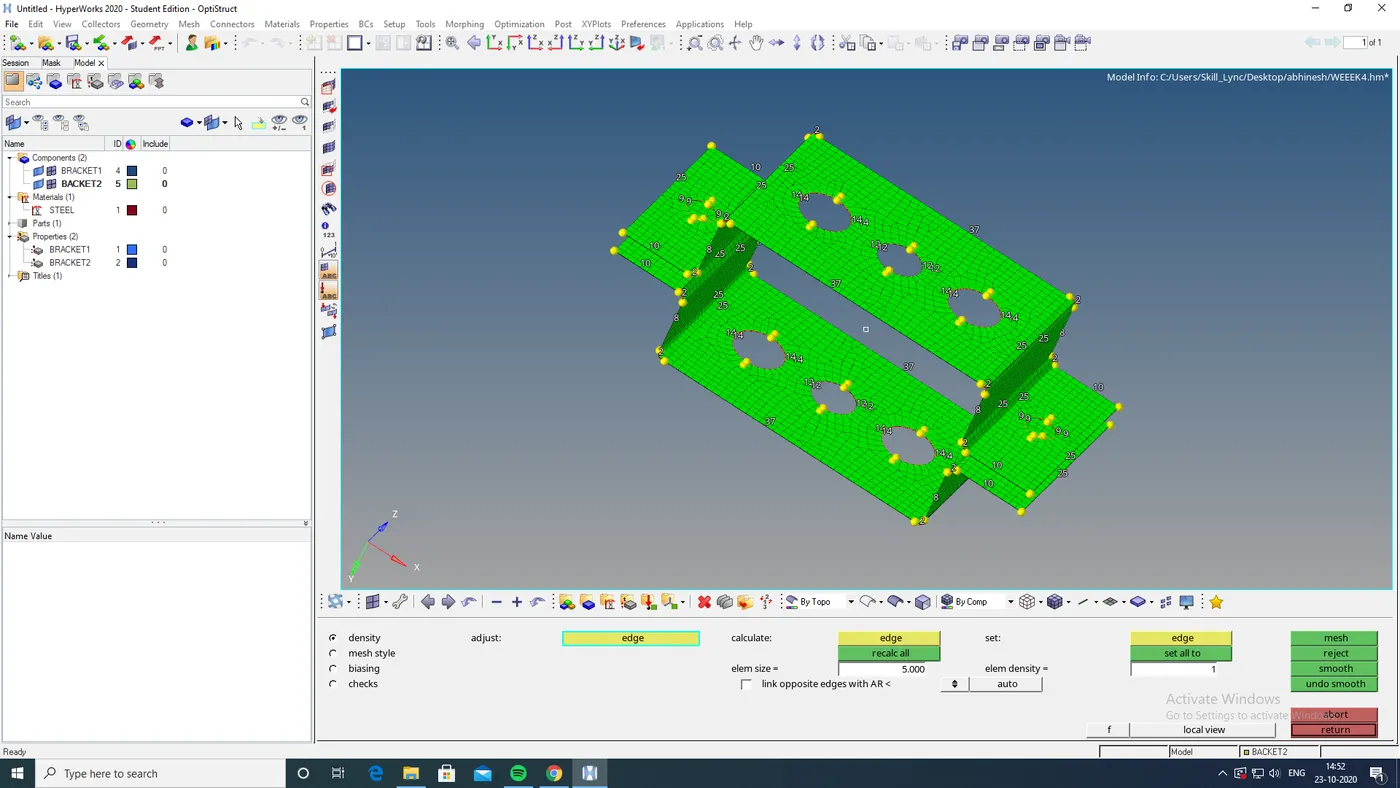
- after meshing it make the washer spilt nodes equal
- and then we hide thae surface.
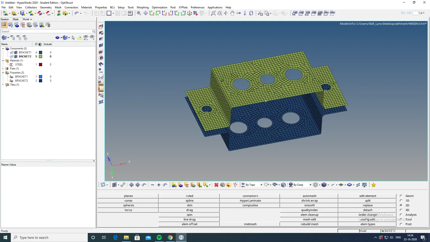
- then i given rbe2 lynk in d and e holes and given mass to them with magnitude 10
- then i given a, b , c with rbe2,rbe3,rbe3 links
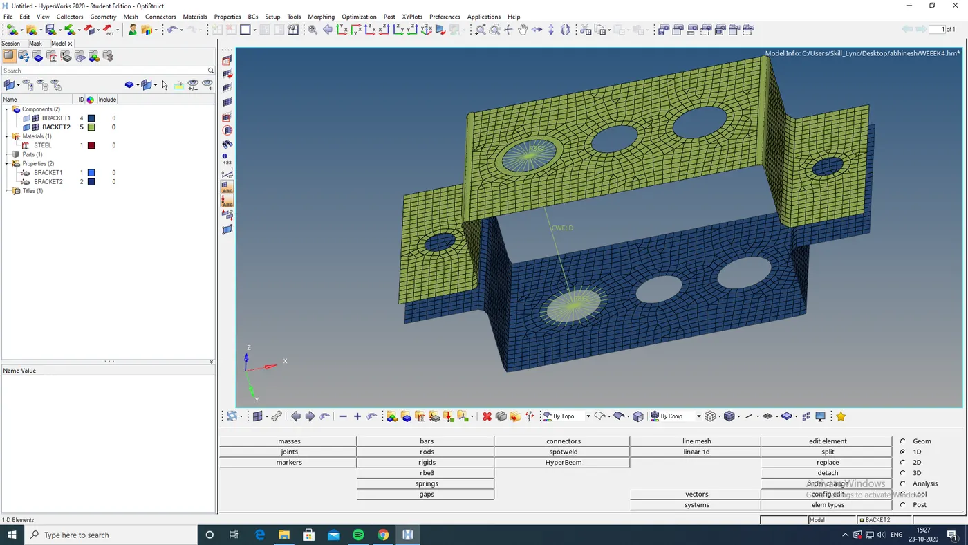
- i had done that with giving the dof for seperate a,b,c holes
- also i given a spring in f bygoing spring option and selecting thole nodes.
- then i given element connect betwen the holes parallel by going rod bar and bar for beam option
- to create beams, rods and bars in cross section i select standard section in hyperbeam option and i select create option
- then the scereen take us another page then we can create those 3 cross sections required by using create option go to standard section and go to optistruct or hypermesh inorder to create the cross sectins needed.
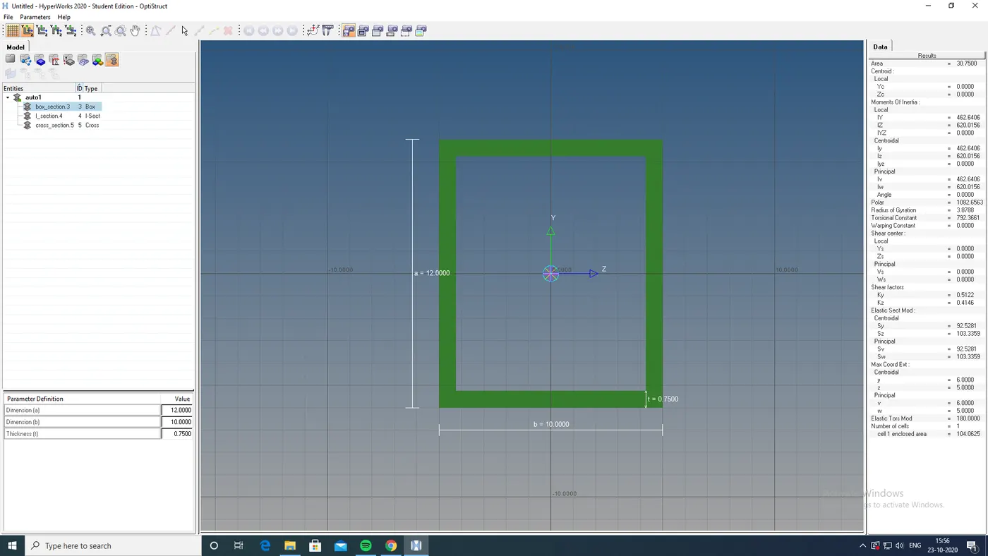
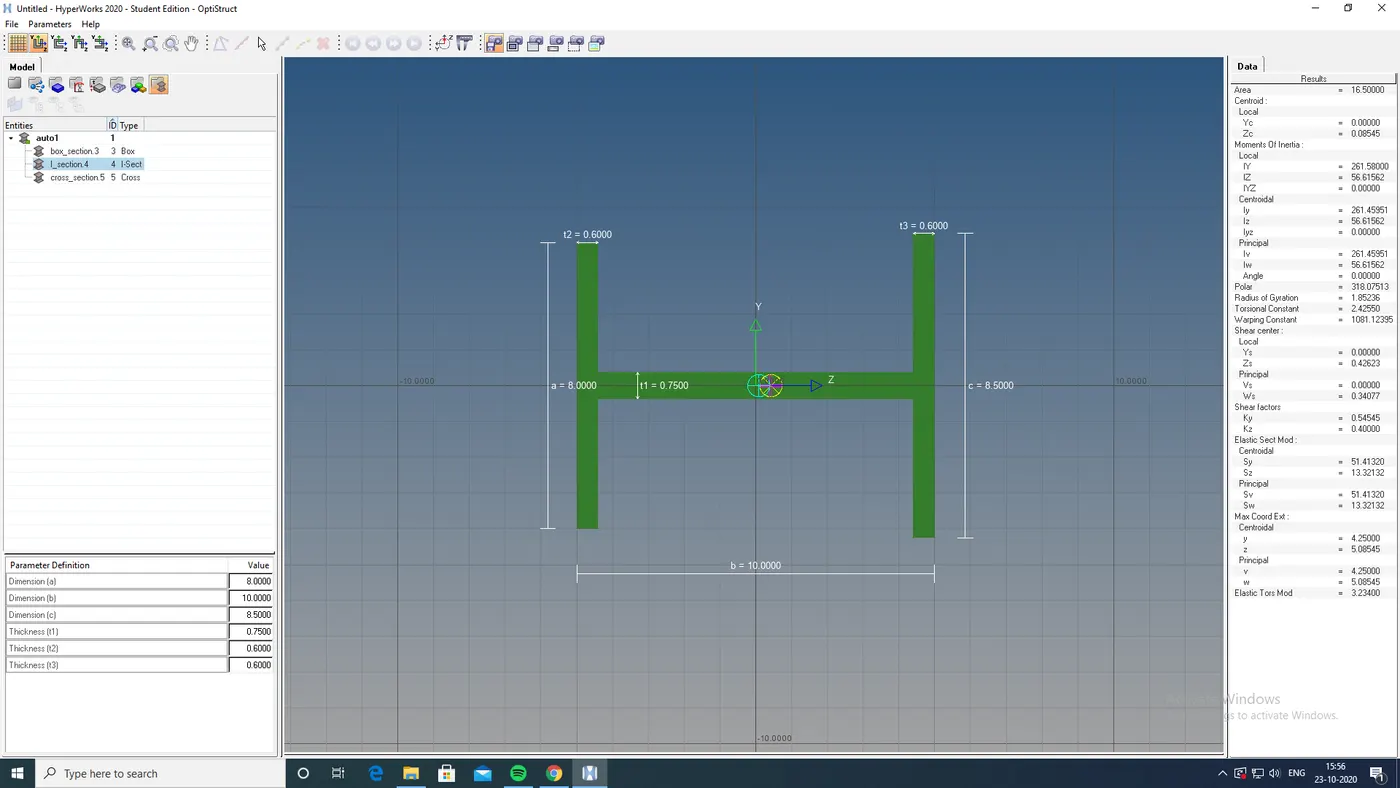
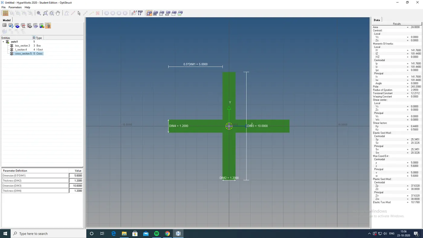
- and give the dimension to the cross sections needed
- then by giving the properties, matterial,cardimage,crosssection and all and then to update in the model
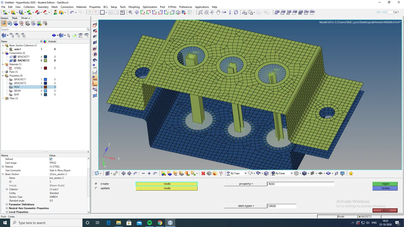
then we got a model with 3 crosssection, with rbe2,rbe3 link,spring attached and with mass respresented.
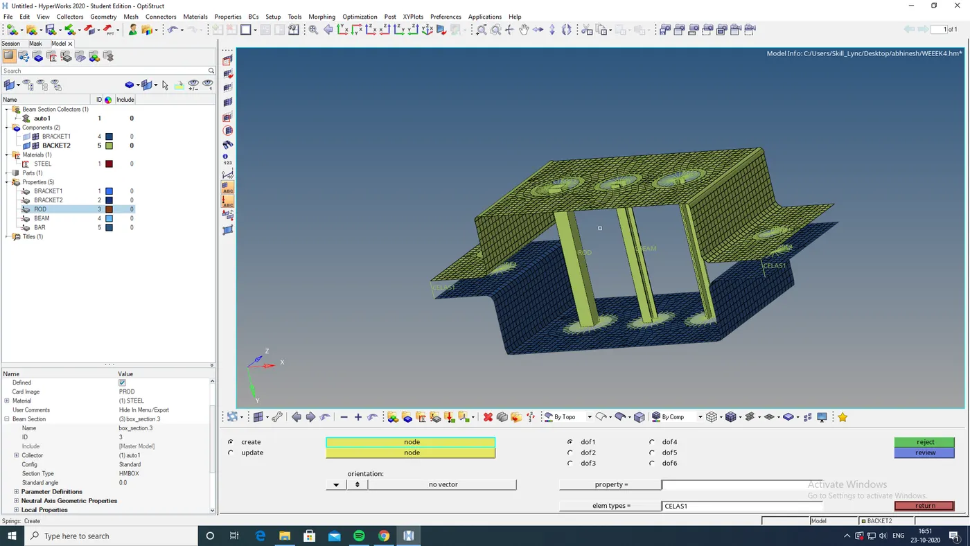
FINAL MODEL IMAGE:
RESULT:
Created 1D elements on the following component with given cross-section and DOF
a. Rod element:- with only translational DOF and RBE2 link
Cross-Section: BOX- Dimension a= 12 mm
dimension b=10 mm
Thickness t= 0.75 mm
b. Beam element:- with all DOF and RBE3 link
Cross-Section: I Section- Dimension a= 8 mm
Dimension b= 10 mm
Dimension c= 8.5 mm
Thickness t1= 0.75 mm
Thickness t2= .6 mm
Thickness t3= .6 mm
c. Bar element:- with only x and y DOFs With RBE3 link
Cross-section: CROSS section- Dimension DIM1= 5 mm
Thickness DIM2= 1.2 mm
Dimension DIM3= 10 mm
Thickness DIM4= 1.2mm
d. & e. apply the mass of magnitude 10 with RBE2 link.