Assignment 1
Objective :
1) To perform Geometric clean up on given models .
2) To extract midsurface .
3) To clean up Geometry of midsurface and to remove holes less than dia = 5mm
4) To mesh the components with given quality criteria .
5) To assign thickness to given models .
Procedure :
Model 1
1) Geometry clean up
The model was impoted and inspected for surface deformations .
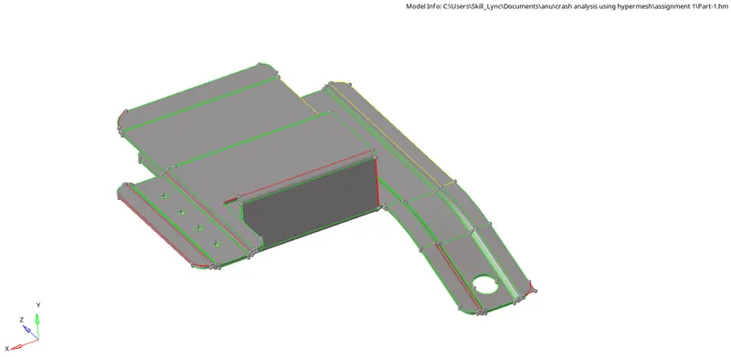
The geometry view mode was changed to by topo to observe for free edges or extra surfaces .
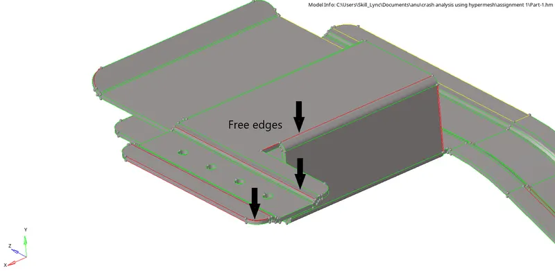
The free edges were rectified using toggle edge function from quick edit panel and replace line option from edge edit panel of geometry module .
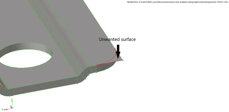
The unwanted surface was also rectified by replace edge function from geometry module .


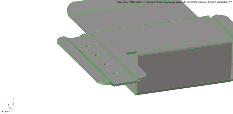
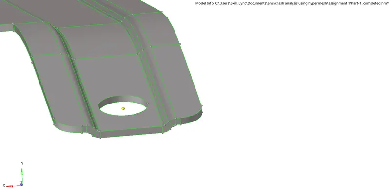
The additional surfaces were cleared by masking and deleting those surfaces using delete function . 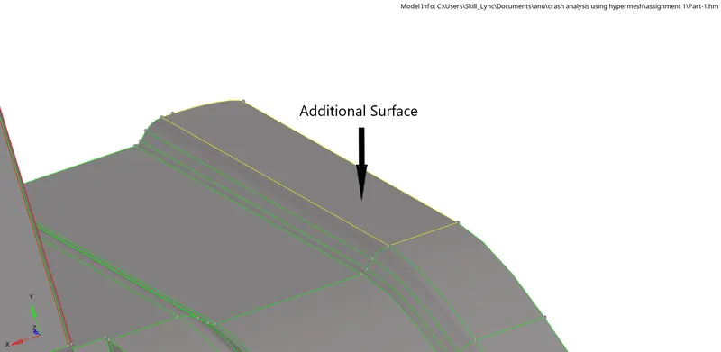
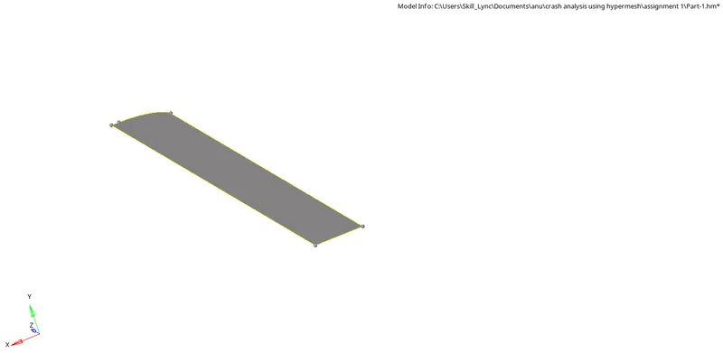

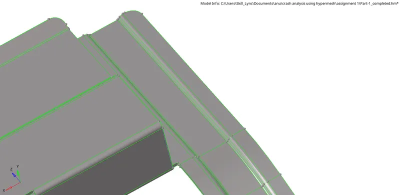
Hence the geometry clean up was completed on parent component .
2) Midsurface
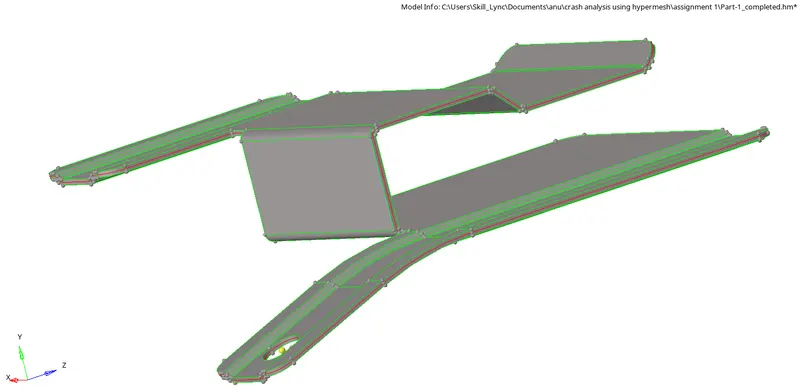
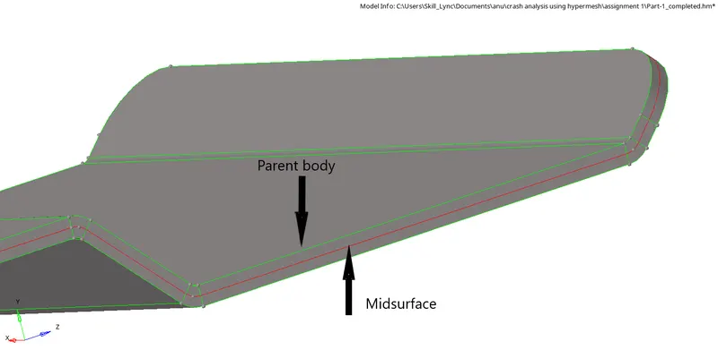
The extract midsurface , automidsurface option from geometry module was used .

3) Geometry clean up on midsurface and remove holes less than 5mm dia .
Geomtery clean up was performed on midsurface using toggle edge function from quick edit panel to toggle edges which were less than minimum element length .
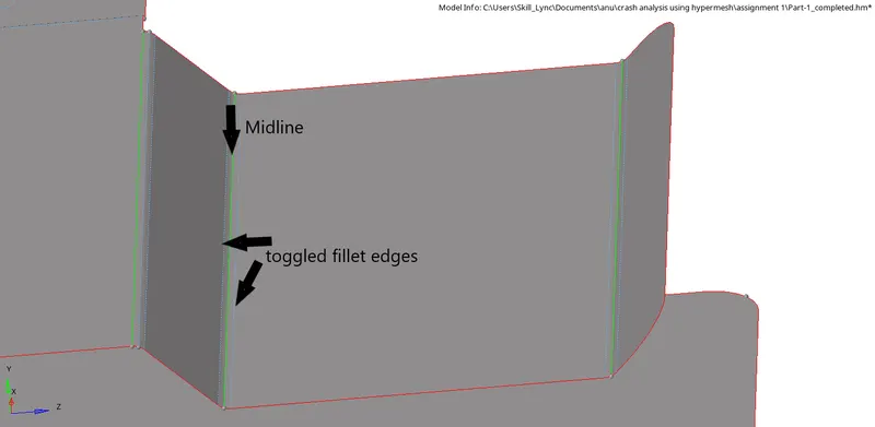
Midlines were created using midline option from lines panel of geometry module .
Fillets were trimmed using trim with free lines (midline ) option from surface edit panel from geometry module and edge lines were toggled.
Holes with diameter less than 5mm dia were removed using filler surface option from quick edit panel .
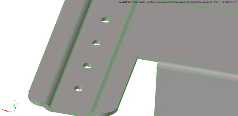
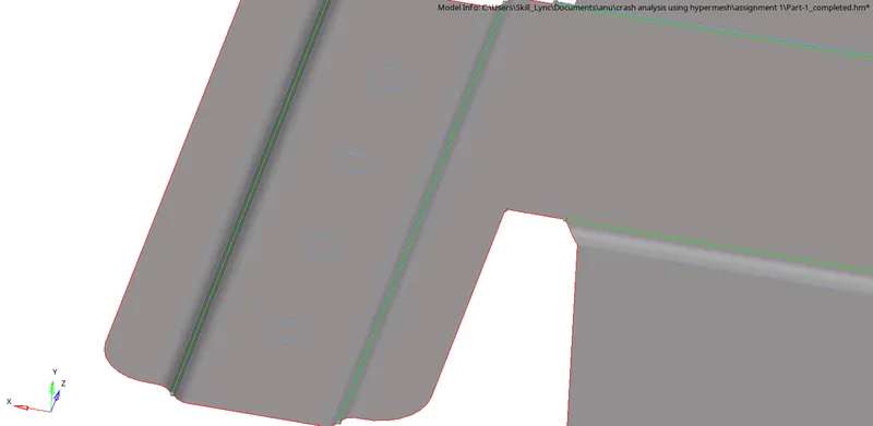


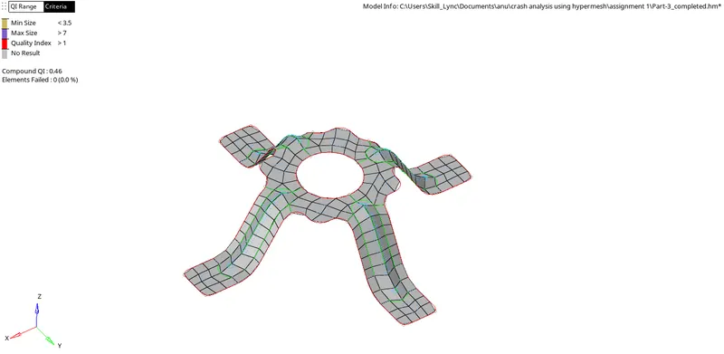
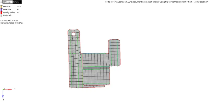
4) Meshing the component with min element lenth =3.5 and max lenth =7 , target length= 5 .
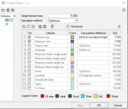
The component was meshed by selecting surfaces and using automesh option from 2D panel with target element length =5 with allign and size option ticked on .

The mesh flow near the hole was rectified using rotate tool from tool module .
The nodes to be rotated were slected , the nodes for selecting plane of rotation was selected and temp node at center of hole was selected as base of rotation .
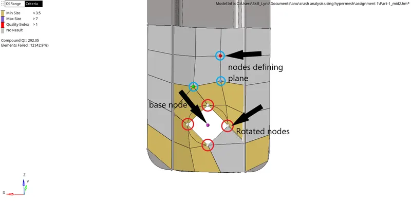

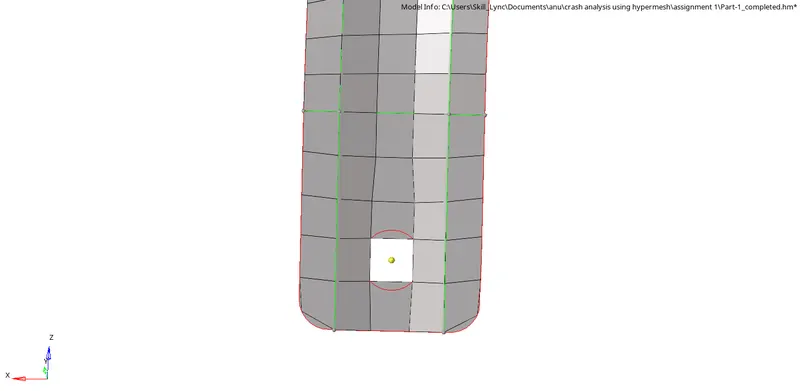
Elements failing for minimum length were rectified using distance option from geomterty module .
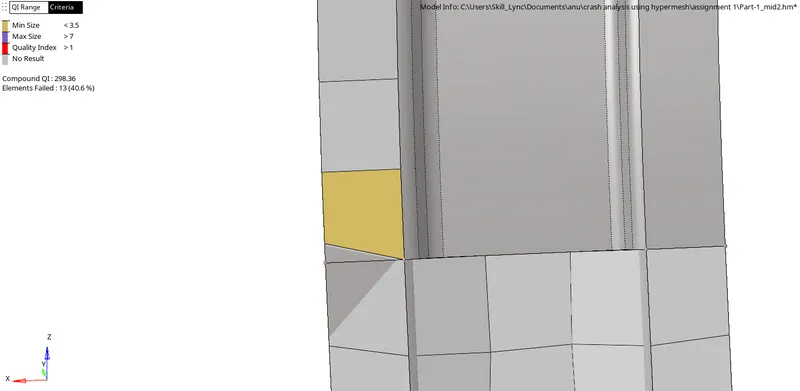

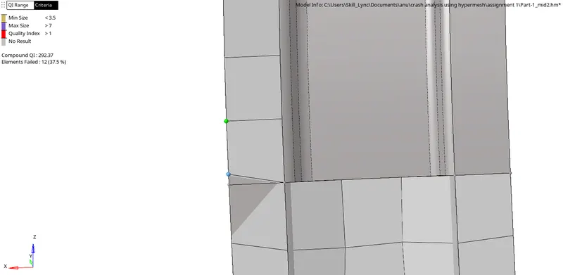
Hence the component was meshed with zero elements failing for quality .
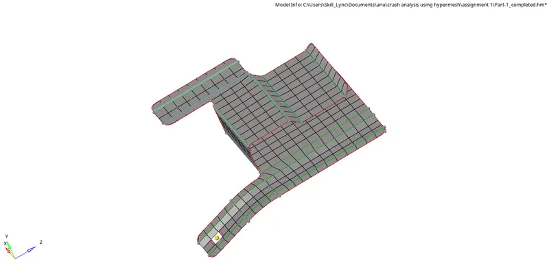
5)Assigning thickness
To assign thickness , the user interface was changed to Radios .
Property was selected and thickness was input as 0.9 units .
The property was assigned to meshed midsurface by right clicking on component and using assign function .
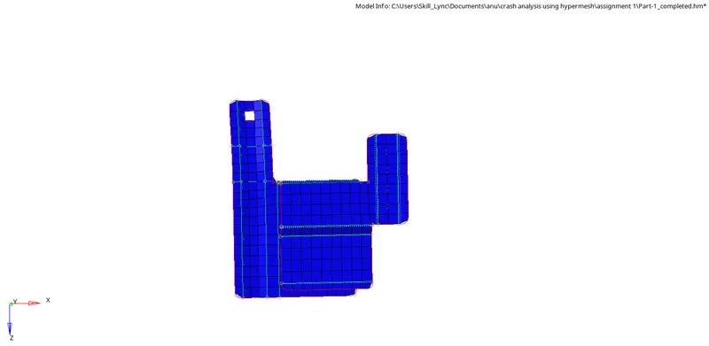
The element view was changed from traditional 2D elements representation to detailed 2D representation to view the thickness assigned .
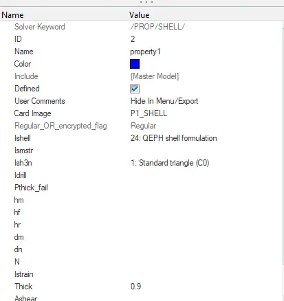
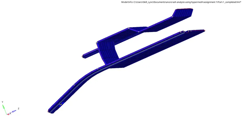
Hence thickness was assigned to the model .
Conclusion :
1) Geometry clean up was performed so as to remove any free edges or additonal surfaces from parent component .
2) Midsurface was extraced
3) Geometry clean up was performed on the midsurface and holes with dia < 5mm were removed .
4) Component was meshed according to given quality criteria .
5) Thickness was assigned to the component .
Procedure :
Model 2
1) Geomtery clean up
The component was imported and inspected for free edges or surface deformations .
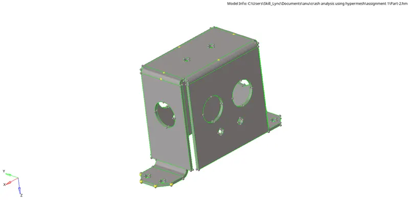
The surfaces too small in length were joined by using replace point function from quick edit panel of geometry module .
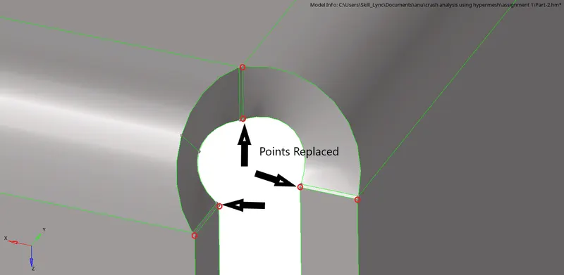

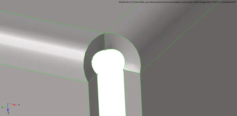
Since there were no free edges in the component , it was ready for midsurface extraction .
2) Midsurface
The extract midsurface , automidsurface option from geometry module was used .
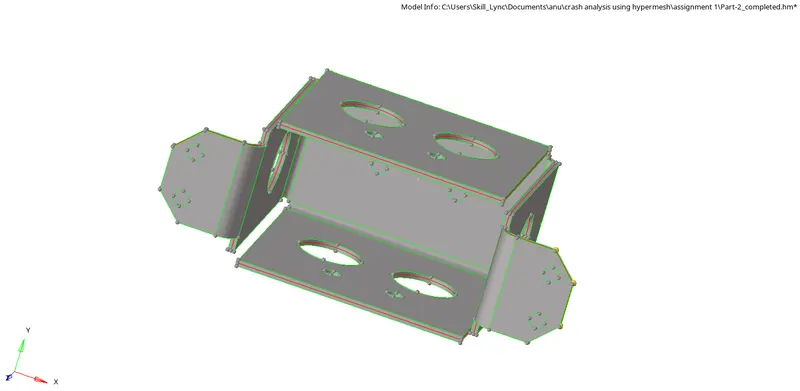
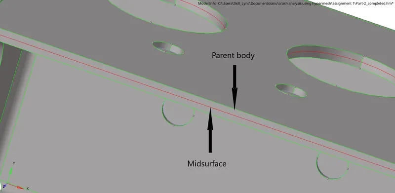
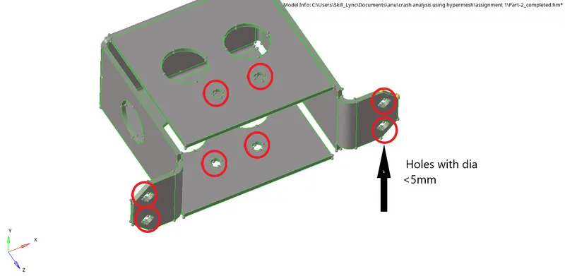
3) Geometry clean up on midsurface and remove holes less than 5mm dia .
Geomtery clean up was performed on midsurface using toggle edge function from quick edit panel to toggle edges which were less than minimum element length .
Holes with diameter less than 5mm dia were removed using filler surface option from quick edit panel.
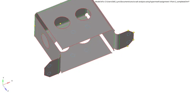

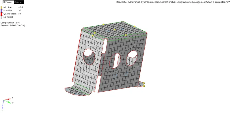
4) Meshing the component with min element lenth =3.5 and max lenth =7 , target length= 5 .
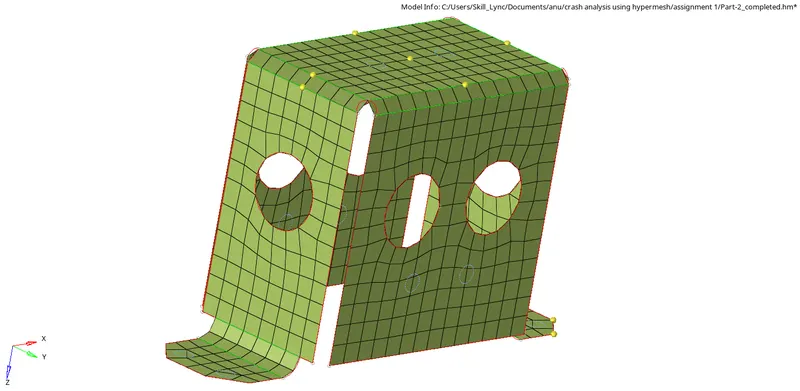
The component was meshed by selecting surfaces and using automesh option from 2D panel with target element length =5 with allign and size option ticked on .
Clean up tools like drag tria, swap edge and smooth from quality index were used to remove trias , cancel opposing trias etc.
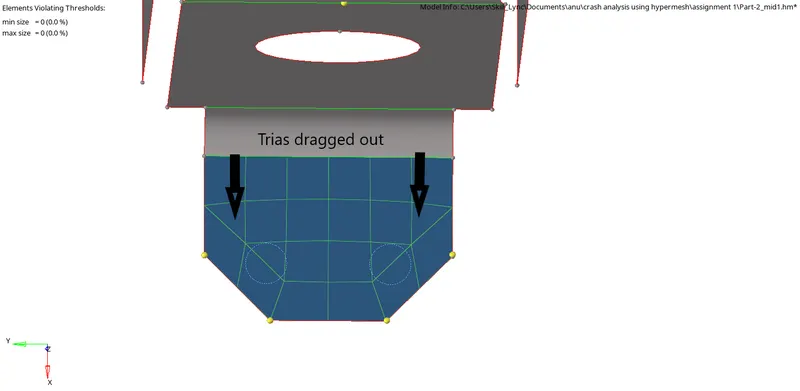
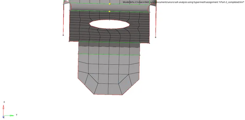
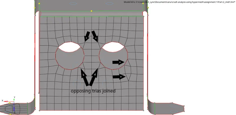
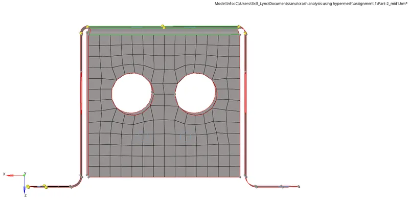
Hence the complete part was meshed with zero elements failing for quality criteria .
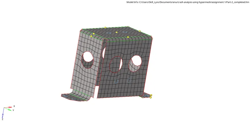
5)Assigning thickness
To assign thickness , the user interface was changed to Radios .
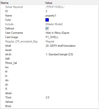
Property was selected and thickness was input as 2 units .
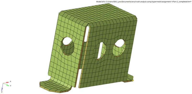
The property was assigned to meshed midsurface by right clicking on component and using assign function .
The element view was changed from traditional 2D elements representation to detailed 2D representation to view the thickness assigned .
Conclusion :
1) Geometry clean up was performed so as to remove any free edges or additonal surfaces from parent component .
2) Midsurface was extraced
3) Geometry clean up was performed on the midsurface and holes with dia < 5mm were removed .
4) Component was meshed according to given quality criteria .
5) Thickness was assigned to the component .
Model 3
Procedure :
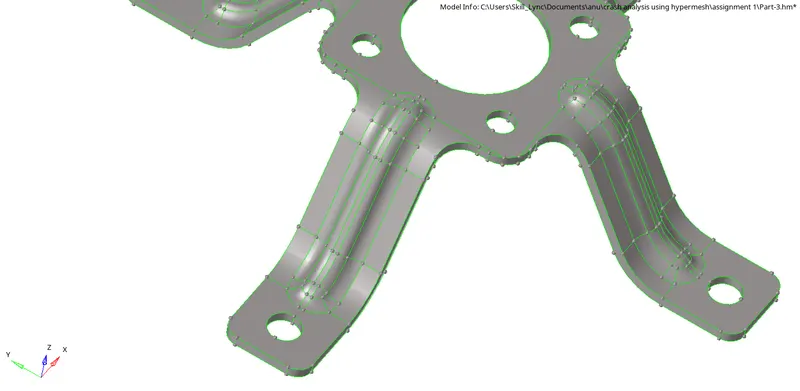
1) Geometry clean up
The given model was imported and visually inspected for surface deformations or freee edges .
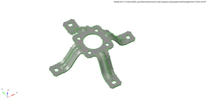
Since there were no free edges or duplicate surfaces , the model was ready for midsurface extraction.
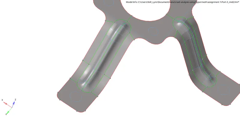
2) Midsurface
The extract midsurface , automidsurface option from geometry module was used .
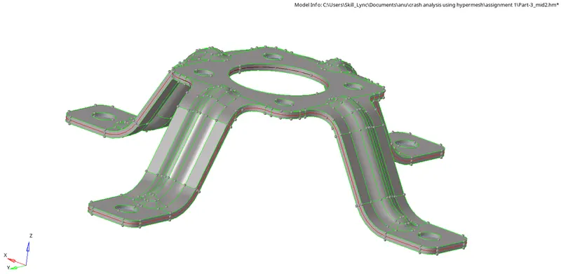
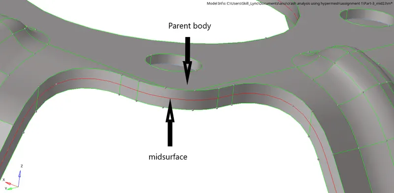
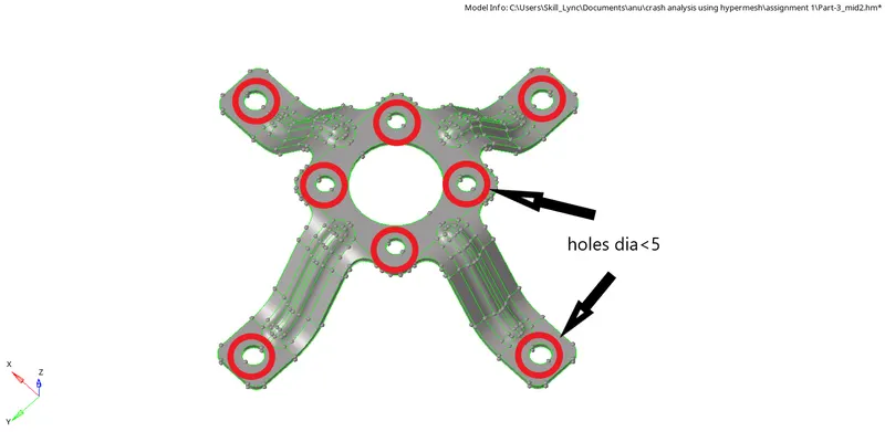
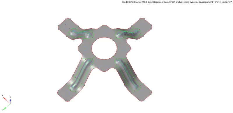
3) Geometry clean up on midsurface and remove holes less than 5mm dia .
Geomtery clean up was performed on midsurface using toggle edge function from quick edit panel to toggle edges which were less than minimum element length .
Holes with diameter less than 5mm dia were removed using filler surface option from quick edit panel.
4) Meshing the component with min element lenth =3.5 and max lenth =7 , target length= 5 .
the component was meshed by selecting surfaces and using automesh option from 2D panel with target element length =5 with allign and size option ticked on .
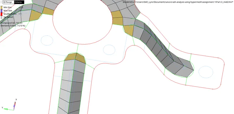
Clean up tools like drag tria, swap edge and smooth from quality index were used to remove trias , cancel opposing trias etc.
Elements failing for minimum length was rectified by using distance option from geometry module .
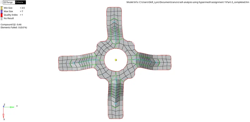
Hence meshing was performed on the component with zero elements failing for quality criteria .
5)Assigning thickness
To assign thickness , the user interface was changed to Radios .
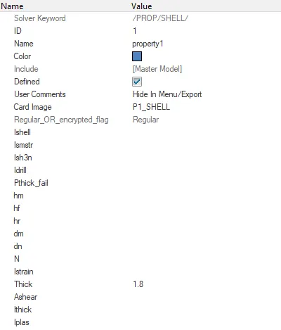
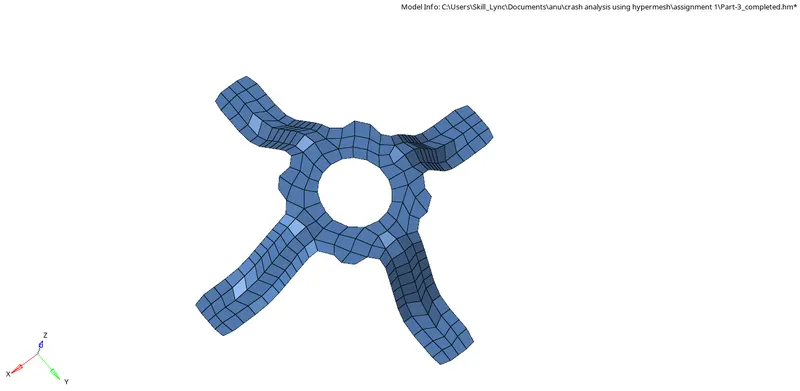
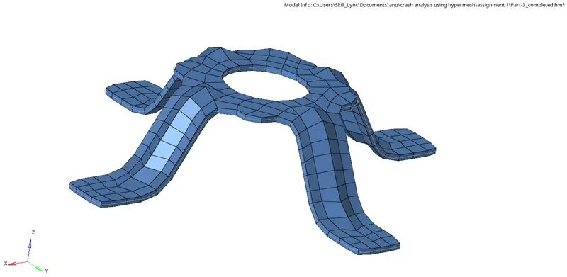
Property was selected and thickness was input as 2 units .
The property was assigned to meshed midsurface by right clicking on component and using assign function .
The element view was changed from traditional 2D elements representation to detailed 2D representation to view the thickness assigned .
Conclusion :
1) Geometry clean up was performed so as to remove any free edges or additonal surfaces from parent component .
2) Midsurface was extraced
3) Geometry clean up was performed on the midsurface and holes with dia < 5mm were removed .
4) Component was meshed according to given quality criteria .
5) Thickness was assigned to the component .