To Cleanup the given geometries and extract the midsurface of the components and assign proper thickness, by creating a generic property in Hypermesh
OBJECTIVE:
To Cleanup the given geometries and extract the midsurface of the components and assign proper thickness, by creating a generic property.
Target element length: 5mm
Minimum element length: 3.5mm
Maximum element length: 7mm
PROCEDURE:
Part 01
1. First of all, go to Import Solver Deck > import Geometry > Choose File > Import. The geometry is imported.
2. Change the geometric color view by Topo.
3. Fix some of the geometric errors by using a quick edit panel and surface panel.
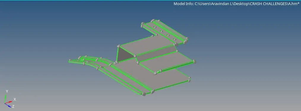
4. To take midsurface go to Geom < Midsurface.
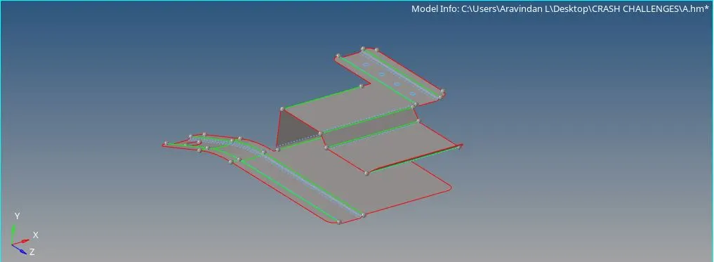
5. After taking midsurface mesh the entire component by 2D < automesh < select surf < element size = 5mm < mesh.
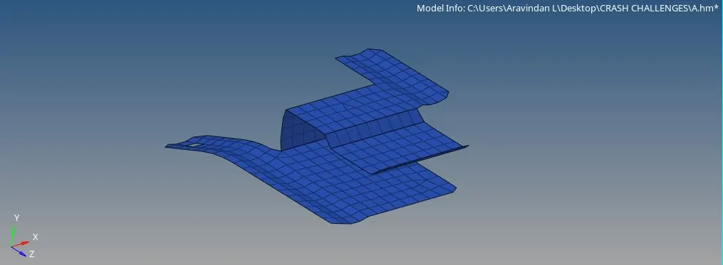
6. Then go to Quality criteria in min element set as 3.5mm and in the max element set as 7mm.
7. Then check the failing elements and rectify them by using these options
- Tool > Check elements > Save Failed.
- Tool > Mask > elems > Retrieve > Mask > Reverse. ( Only the failed elements will be shown in the display )
- F12 > elems > Select elements > Mesh ( Some failed elements can be removed by remeshing them )
- 2d > Qualityindex > cleanup tools > Display Threshold : fail > there are lot of options there in cleanup tools, By using these option we can remove the failed elements.
8. To assign the thickness of the component, first of all, we have to know the exact thickness of the component so unhide your parent geometry and press the F4 key and select two-point option and select one point on the top and select another point on the bottom of the surface and note the overall thickness value.
9. Go to the feature tree and create a property and choose the card image as PSHELL in the Thickness area type the value.
10. And then select the particular component and then assign the property.
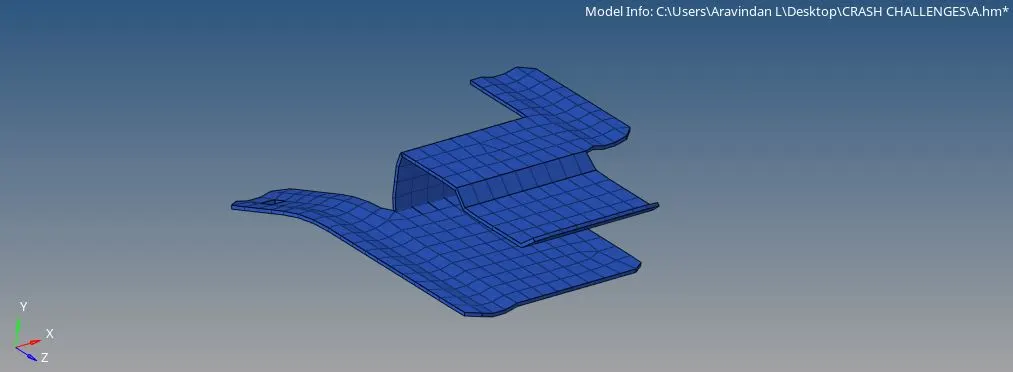
11. To check whether the property is correctly assigned in the graphic window below there will 2D traditional element representation in that select 2D detailed element representation.
in the display, if it shows the thickness of the elements then the thickness is assigned or else we would have made some mistakes in our past process.
Part 02
1. First of all, go to Import Solver Deck > import Geometry > Choose File > Import. The geometry is imported.
2. Change the geometric color view by Topo.
3. Fix some of the geometric errors by using a quick edit panel and surface panel.
4. To take midsurface go to Geom < Midsurface.
5. After taking midsurface mesh the entire component by 2D < automesh < select surf < element size = 5mm < mesh.
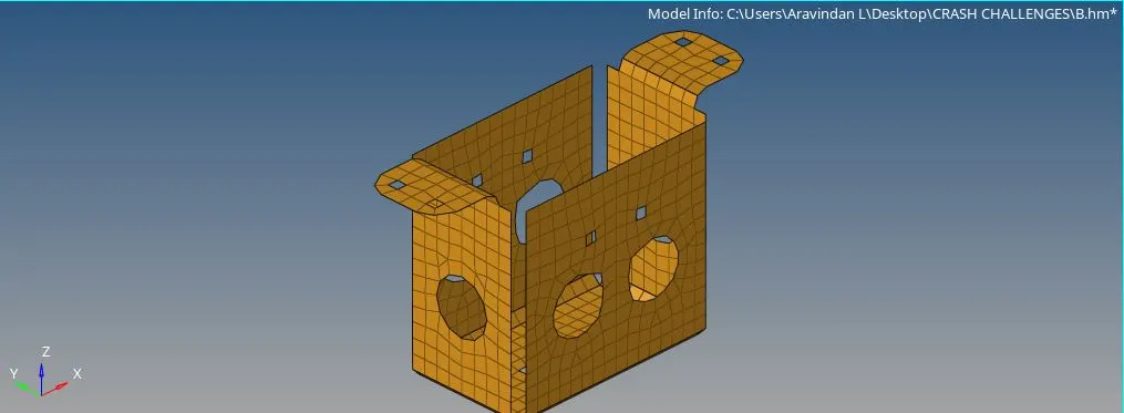
6. Then go to Quality criteria in min element set as 3.5mm and in the max element set as 7mm.
7. Then check the failing elements and rectify them by using these options
- Tool > Check elements > Save Failed.
- Tool > Mask > elems > Retrieve > Mask > Reverse. ( Only the failed elements will be shown in the display )
- F12 > elems > Select elements > Mesh ( Some failed elements can be removed by remeshing them )
- 2d > Qualityindex > cleanup tools > Display Threshold : fail > there are lot of options there in cleanup tools, By using these option we can remove the failed elements.
8. To assign the thickness of the component, first of all, we have to know the exact thickness of the component so unhide your parent geometry and press the F4 key and select two-point option and select one point on the top and select another point on the bottom of the surface and note the overall thickness value.
9. Go to the feature tree and create a property and choose the card image as PSHELL in the Thickness area type the value.
10. And then select the particular component and then assign the property.
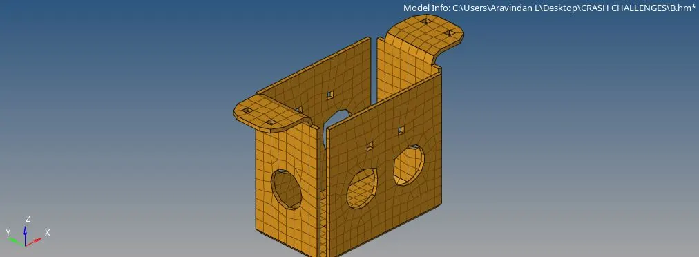
11. To check whether the property is correctly assigned in the graphic window below there will 2D traditional element representation in that select 2D detailed element representation.
in the display, if it shows the thickness of the elements then the thickness is assigned or else we would have made some mistakes in our past process.
Part 03
1. First of all, go to Import Solver Deck > import Geometry > Choose File > Import. The geometry is imported.
2. Change the geometric color view by Topo.
3. Fix some of the geometric errors by using a quick edit panel and surface panel.
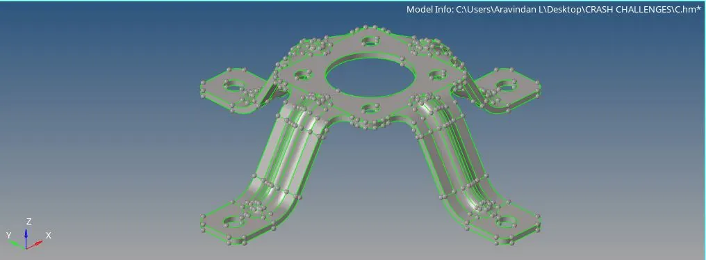
4. To take midsurface go to Geom < Midsurface.
5. After taking midsurface mesh the entire component by 2D < automesh < select surf < element size = 5mm < mesh.
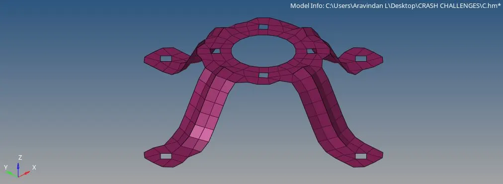
6. Then go to Quality criteria in min element set as 3.5mm and in the max element set as 7mm.
7. Then check the failing elements and rectify them by using these options
- Tool > Check elements > Save Failed.
- Tool > Mask > elems > Retrieve > Mask > Reverse. ( Only the failed elements will be shown in the display )
- F12 > elems > Select elements > Mesh ( Some failed elements can be removed by remeshing them )
- 2d > Qualityindex > cleanup tools > Display Threshold : fail > there are lot of options there in cleanup tools, By using these option we can remove the failed elements.
8. To assign the thickness of the component, first of all, we have to know the exact thickness of the component so unhide your parent geometry and press the F4 key and select two-point option and select one point on the top and select another point on the bottom of the surface and note the overall thickness value.
9. Go to the feature tree and create a property and choose the card image as PSHELL in the Thickness area type the value.
10. And then select the particular component and then assign the property.
11. To check whether the property is correctly assigned in the graphic window below there will 2D traditional element representation in that select 2D detailed element representation.
in the display, if it shows the thickness of the elements then the thickness is assigned or else we would have made some mistakes in our past process.
RESULT:
Therefore we have learned to clean up the geometry, taking midsurface and assigning thickness of the component.