Assembly of Yacht
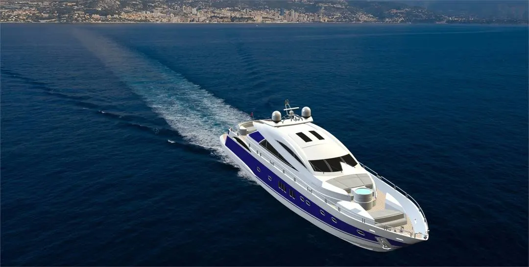
DESIGNING, MODELING, ASSEMBLY AND PHOTO-REALISTIC RENDERING OF SUNSEEKER PREDATOR YACHT
OBJECTIVES
- Using SolidWorks to model the parts of a Sunseeker Predator Yacht.
- Using Solidworks to assemble all the parts.
- Give the parts in solidworks an appropriate appearance.
- Use Photoview 360 to render images.
INTRODUCTION
SolidWorks is a 3D modeling software that is used to design parts of a model and assemble them into a finished product and are used in many industries such as automotive, aeronautics, etc. SolidWorks is a platform for parametric modeling that allows the model to be modified in size at any time. A Sunseeker Predeator Yacht is modeled for this project with
1. Propeller 2. Radar 3. Hull 4. Garage Door 5. Front, Middle and Rear seat 6. Superstructure 7. Radar mast.
The yacht is assembled in solidworks after designing these components. For rendering, the assembled yacht model is then used.
DESIGN METHODOLOGY
- Designing various Components/ Parts
- Assembly of Components/ Parts
- Applying Decals, Appearances, Camera, Lights, Scenes
- Rendering
PARTS TO BE MODELED
1. Propeller
2. Radar
3. Hull
4. Garage Door
5. Front seat
6. Middle seat
7. Rear seat
8. Superstructure
9. Radar Mast
TOOLS AND FEATURES USED
1. Line : This feature enables us to create a straight line. A solid line or a construction line can be sketched.
2. Circle : This feature enables us to sketch circles.
3. Rectangle : This feature enables us to sketch rectangles or squares.
4. Spline : This feature enables us to create curved lines.
5. Arc : This feature allows us to sketch arc.
6. Extend : This feature makes it possible for us to extend the sketches.
7. Trim : This feature is used to trim sketches.
8. Split : Using a sketch, this feature is used to split bodies.
9. Projected curve : In this feature, two sketches are used to make a curve.
10. Extrude bose : This feature enables us to generate solid bodies using a sketch.
11. Extrude cut : This feature enables us to create cuts or holes in the solid body of any shape.
12. Swept bose : This feature enables us to create a solid body along a curve path or create a solid curved body.
13. Mirror : This feature allows us to choose a reference plane or face to produce carbon replica of the solid body.
14. Revolve : This facilitates us to produce a revolve solid body around an axis.
15. Linear pattern : It enables us to create a pattern in a straight line.
16. Circular pattern : This allows us to create a pattern of a circular path.
17. Shell : This is used to make a solid body to hollow.
18. Split Entities : This is used to split a line into two sections or more.
19. Mirror Entities : This is used to create a sketch mirror.
20. Dome : This feature is used over a flat solid body to create a dome shaped solid.
21. Loft : This feature allows us to create solid bodies with an uneven geometry.
22. Plane : To create new plane using one or more references, this feature is used.
23. Chamfer : This feature is used to create edges that are inclined.
24 : Fillet : This is used to create edges that are circular.
SURFACE FEATURES
25. Extruded surface : This is used to create a surface out of a sketch.
26. Lofted surface : This is used to create an uneven surface using one or more edges or sketches.
27. Trim surface : This is used to cut surfaces.
28. Surface sweep : This is used along a curve or a line to create a surface.
29. Boundary surface : This is used to create a boundary surface (i.e)., a surface formed using one or more boundary edges.
30. Ruled surface : This is used to create surfaces from the edges.
31. Extend surface : This is used to extend the surface that exists.
32. Offset surface : This is used for any surface to be offset.
DESCRIPTION
A yacht referred to as a boat could've been heard, but not all boats are yachts. Technically speaking, a yacht is a boat that floats on the sea. But a boat has to be at least 35 feet long to be considered a yacht. Yachts can also be much larger than that a mega-yacht is more than 100 feet long, whereas super-yachts are considered that are longer than 200 feet. Typically, yachts are used for leisure and are built to be luxurious. These boat types often have powerful motors that allow them to travel long distances easily, but they may be wind-powered traditional sailing yachts. Other types of boats include fishing boats, which are boats constructed to be sufficiently robust to endure hours of fishing in either fresh or salt water, and rowboats, small boats that are usually designed to be propelled with oars, often used in shallow water.
The main parts of a SUNSEEKER PREDATOR YACHT are as follows,
- Propeller
- Radar
- Hull
- Garage Door
- Front seat
- Middle seat
- Rear seat
- Superstructure
- Radar Mast
PARTS MODELED
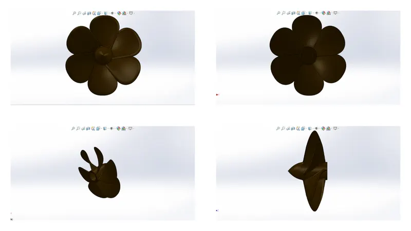
1. PROPELLER
The propeller provides the thrust for the acceleration of the yacht. It is primarily mounted at the end of the yacht and with the support of a shaft, is connected directly to the engine.
Tool and Features used:
- Sketch
- Line
- Circle
- Loft
- Rectangle
- Revolve
- Cirular Pattern
- Fillet
- Extrude cut
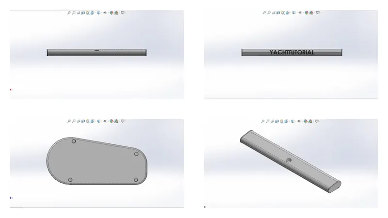
2. RADAR
It is a device which is used to communicate while the yacht is sailing. It is used for transmitting signals and receiving them.
Tools and features used:
- Sketch
- Extrude
- Fillet
- Line
- Polygon
- Circle
- Text
- Mirror
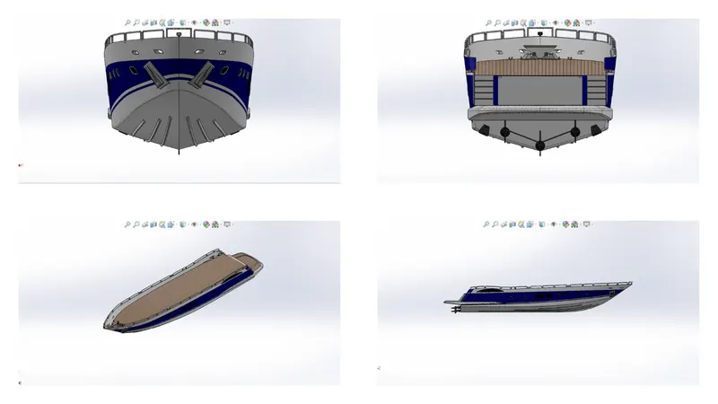
3. HULL
It is the yacht's main body. Supporting all the other objects should be rigid.
Tools and Features used:
- Sketch
- Line
- Circle
- Projected Curves
- Linear Pattern
- Mirror
- Surface Extrude
- Surface Loft
- Extrude Cut
- Fillet
- Chamfer
- Sweep Surface
- KnitSurfae
- Trim
- Offset
- 3D Sketch
- Plane
- Shell
- Helix
4. GARAGE DOOR
It is the door to the yacht's storage space.
Tools and features used:
- Extrude cut
- Mirror
- Text
- Fillet
- Shell
- Plane
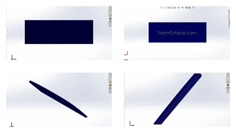
5. FRONT SEAT
For the comfort of the passengers, it is positioned at the front end of the yacht.
Tools and features used:
- Plane
- Sweep Surface
- Loft Surface
- Trim
- Extrude Cut
- Revolve
- Surface Knit
- Surface Fill
- Dome
- Mirror
- Fillet
- Chamfer
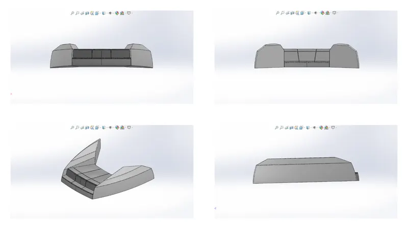
6. MIDDLE SEAT
It is at the middle of the yacht for passengers luxury and comfort.
Tools and features used:
- Extrude Bose
- Chamfer
- Fillet
- Mirror
- Line
- Rectangle
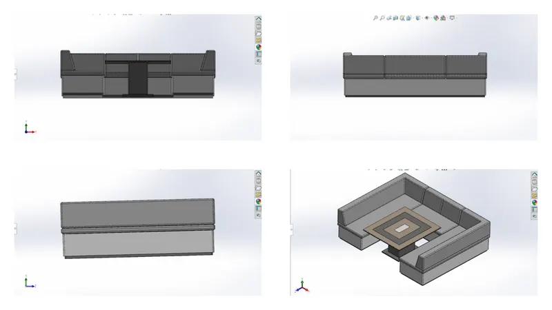
7. REAR SEAT
For passenger comfort, it is located on the rear side of the yacht.
Tools and features used:
- Surface loft
- Surface extrude
- Surface Offset
- Surface trim
- Sweep
- Ruled Surface
- Surface Extend
- Surface Knit
- Surface Extend
- Extrude Bose
- Chamfer
- Extrude Cut
- Mirror
- Plane
- Fillet
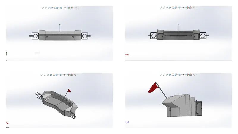
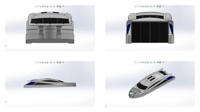
8. SUPERSTRUCTURE
It is the structure designed on the hull. It is the largest compartment for goods and passengers.
Tools and Features used:
- Line
- Spline
- Circle
- Extrude cut
- Projected curves
- Offset
- Surface Fill
- Surface Extrude
- Surface Sweep
- Dome
- Surface Trim
- Extend Surface
- Surface Knit
- Plane
- Ruled Surface
- Split Entities
- Split Lines
- Delete Faces
- Fillet
- Chamfer
- Mirror
9. RADAR MAST
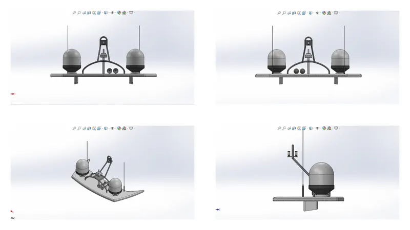
It is the structure which supports the radar.
Tools and the features used:
- Spline
- Extrude Bose
- Revolve
- Circle
- Mirror
- Line
- Fillet
- Chamfer
- Shell
- Projected curve
ASSEMBLY OF SUNSEEKER PREDATOR YACHT
MAIN ASSEMBLY :
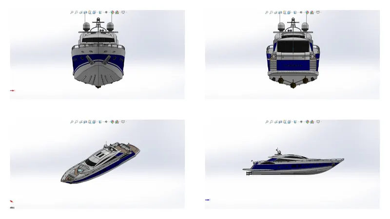
The hull part is initially inserted into the assembly using the insert parts option. After that, the part is placed into the assembly environment and is fixed by clicking OK. Then the other parts of the yacht are then placed into the assembly and the possible conditions are given for mate.
FEATURES USED IN ASSEMBLY :
- Mates
- Insert part
- MATES
Mates establish geometric relationships between components of the assembly. We define the permissible directions of linear or rotational motion of the components as we add mates. Within their degrees of freedom, we can transfer a component, envisioning the behaviour of the assembly.
- INSERT PARTS
In this feature, the other components that need to be mated with the prime fixed component can be added.
RENDERING
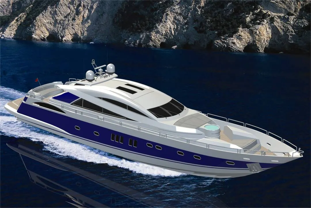
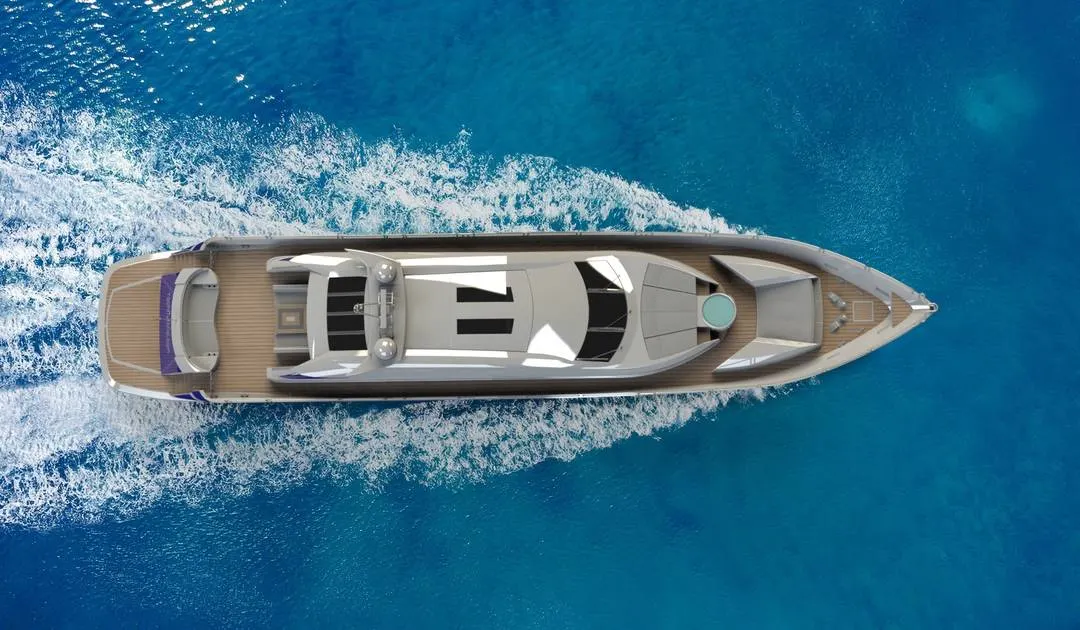
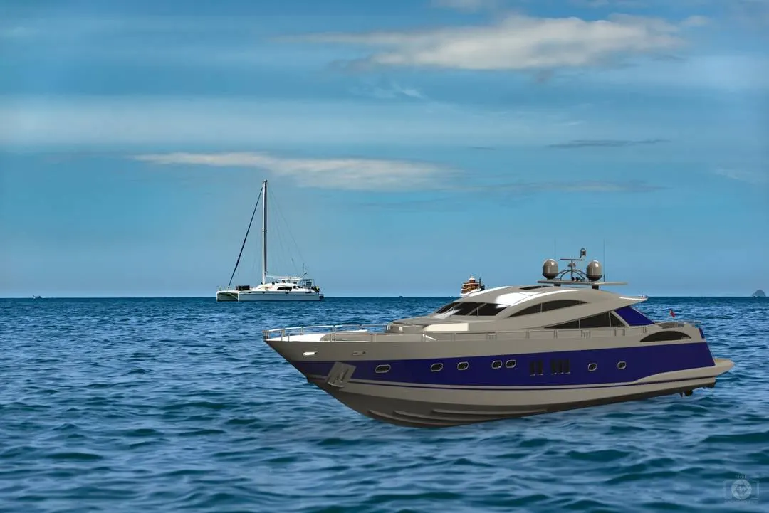
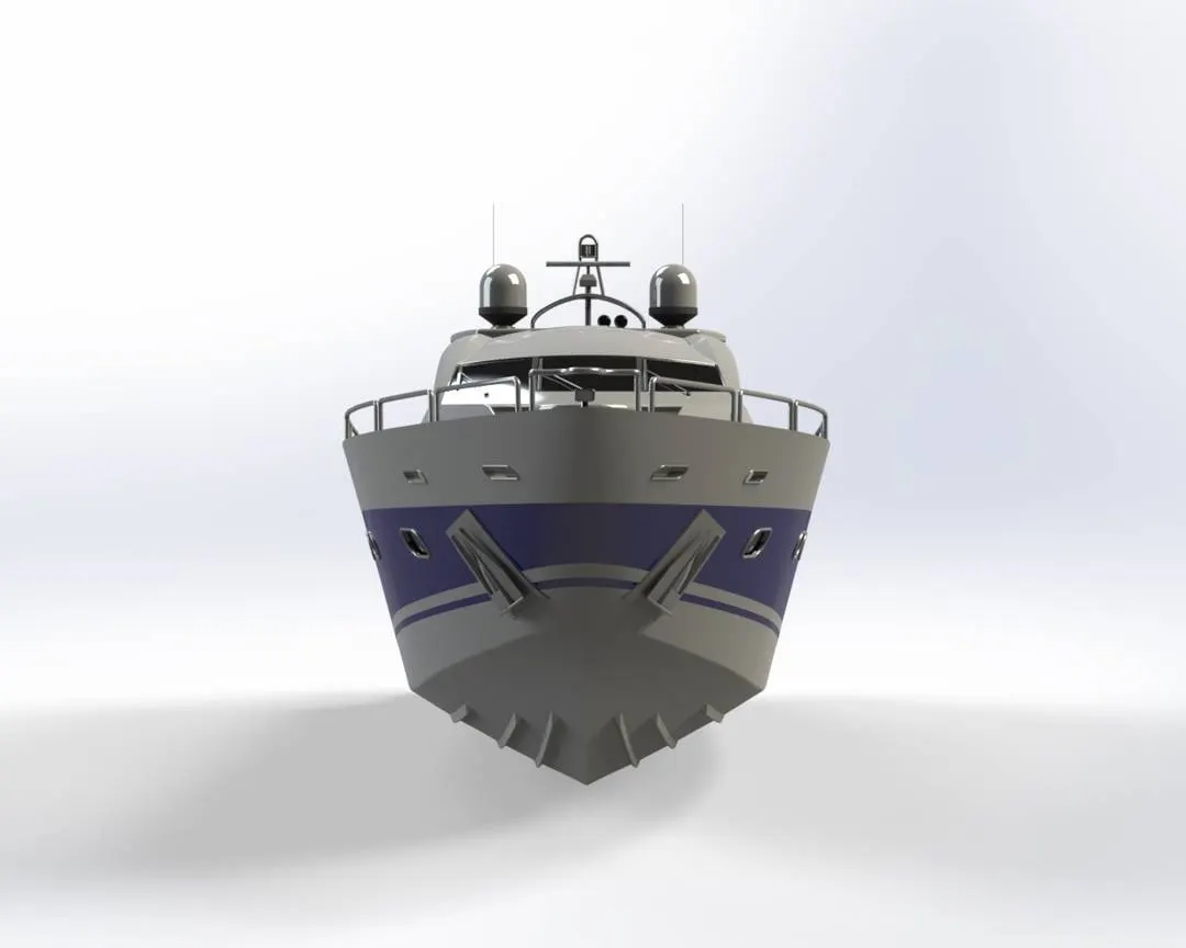
1. Rendering is the method by which the photorealistic model creates realistic images of the environment.
2. In solid works, rendering is performed in two ways. The two ways are as follows,
Photo view 360
Solid-works Visualize
3. Some of the mate conditions and locations are adjusted in the photo-realistic model to make realistic models.
4. Then, with various views, the photo-realistic model is turned into realistic images.
5. I used both Photo-view 360 and Visualise to render the assembled model here.
CONCLUSION
1. The parts of the Sunseeker Predator Yacht are modeled.
2. The parts are inserted into the assembly environment and assembled into an Sunseeker Predator Yacht.
3. With the use of Photo-view 360 and Solidworks Visualise, the photo-realistic image was rendered.
I would like to thank Mr. Soundar Rajan, my mentor, for helping me with the difficulties that I personally experienced while modelling this Sunseeker predator yacht.