Week 9-Creation of 1D Connectors Challenge
OBJECTIVE :
To create a mesh for the given components and create connectors for the respective components as given.
PROCEDURE :
- To import the given .hm file in Hypermesh window and to check for the available components.
- The geometry color mode is changed to by topo mode and the surface is switched to wireframe geometry. The element color mode is also changed to by component mode.
- The components that are given in the file are to be meshed by using the automesh option (2D mesh) in the 2D panel.
- The mesh created should satisfy the quality criteria that is given in the question and the quality criteria is fed in the criteria file settings of the file. The elements failing for quality criteria are checked by using the check elements option in the tools panel.
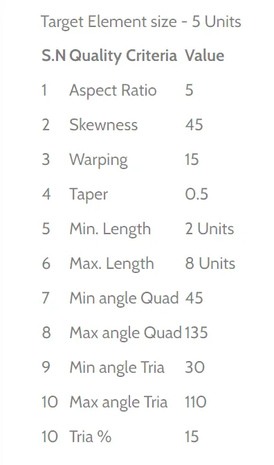
- After meshing the connectors are to be created for the respective components as given in the question.
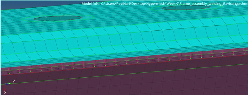
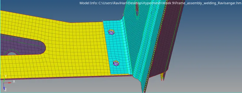
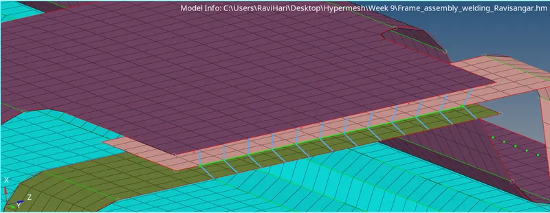
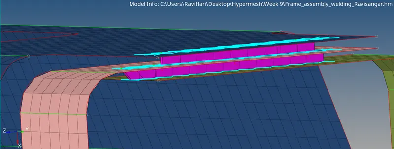
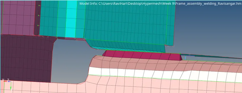
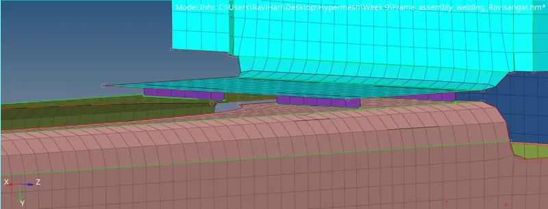
- The connectors are of various types including 1D, 2D & 3D and some of those that are used in the given components are as follows : Seam - quad(angled+capped+L/T), quads, hexa (adhesive); Spot weld; Spot-weld with rigid elements/spring elements and Bolt connectors.
- On adding connectors most of the mesh gets distorted and thus the improper mesh are remeshed properly such that the quality criteria is accepted by the mesh.
- Then the components are checked for the connectors at all the joining areas and if any connectors are not available in the required area then the suitable connectors are used there.
- Thus the given components are meshed and connectors are used in the mentioned components.
FINAL CAD MODEL IMAGES :
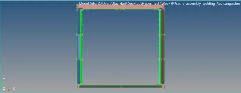
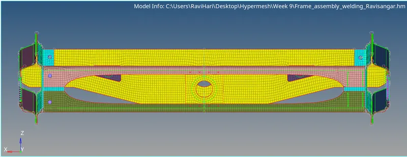
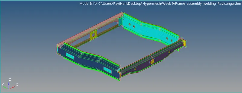
CONNECTORS :
SPOT-WELD :
BOLT CONNECTORS :
SPOT WELD WITH 2 LAYERS :
HEXA ADHESIVE :
SEAM - QUAD (ANGLED+CAPPED+L) :
QUADS :
CONCLUSION :
Thus the given components are meshed by following the quality criteria and connectors are added as mentioned above to the respective components successfully.