SOLIDWORKS_PROJECT 2 - MODELLING AND RENDERING OF LUXURY YACHT
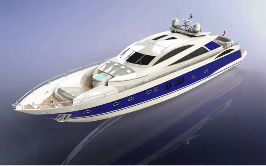
Modelling and Rendering of luxury yacht by using Solidworks
INTRODUCTION:
- The objective of this project is to learn the basic and advanced tools & commands in solidworks.
- To create a separate exterior components in yacht.
- To assemble the all created parts of yacht in solidworks assembly.
- To render and give realistic view to yacht with suitable environment in solid works visualize and Photoview360.
PART MODELLING :
In part modelling, we can create the Individual parts in the chopper in solidworks. These are the following parts in the American chopper.
- Superstructure
- Hull
- Front seat
- Middle seat
- Rear seat
- Radar
- Propellor
- Radar mast
- Garage door
FEATURES USED TO DESIGN FOLLOWING PARTS :
SKETCH:
- Sketch is the 2 dimensional representation of the model with respect to the plane/view from the outside of the model. In solid works there are different sketch options available to create a sketch. These are known as Entities in solid works. The following are the entities available in solid works Line, Arc, Spline, Circles, Rectangle,etc.
OFFSET:
- One or more sketch entities, selected model edges, or model faces by a specified mentioned distance. For example, you can offset sketch entities such as splines or arcs, sets of model edges, loops, and so on. You can offset finite lines, arcs, and splines.
EXTRUDE BOSS/BASS:
- Extrude is a type of 3D feature available in solid works to convert a 2D sketch into the 3D model.
FILLET:
- Fillet/Round creates a rounded internal or external on particular edge or even to the phase. You can fillet all edges of a face, selected sets of faces, selected edges, or edge loops.
CHAMPER:
- It is also like as fillet, but inteed of round edge it forms the sharp edges to tha the face that we select.
LOFTED BOSS/BASS:
- The loft feature allows you generate complex geometry in a single simple feature. It does this by combining the surfaces between various cross-sections of a model. These cross-sections can be sketches, faces, or edges. In the loft interface, these cross-sections are considered “Loft Profiles”.
DOME:
- Select one or more planar or non-planar faces. You can apply domes to faces whose centroid lies outside the face. This allows you to apply domes to irregularly shaped contours.
EXTRUDE CUT:
- Extrude cut is another cool feature which helps to remove materials from the 3D model. It is just the opposite to extrude boss/base feature, because it cuts a sketch profile while extruding. You can cut in both directions and mainly used for creating holes, channels, slots etc.
SPLIT:
- The Split tool is used to project an entity (sketch, solid, surface, face, plane, or surface spline) onto other surfaces or curved/planar faces. You are also able to split faces on multiple bodies with one command.
TRIM ENTITIES:
- Select the trim type based on the entities you want to trim or extend. All trim types are available with 2D sketches and 2D sketches on 3D planes. You can use any of the following trim options: Power trim.
REVOLVE:
- To create a revolve feature: Create a sketch that contains one or more profiles and a centerline, line, or edge to use as the axis around which the feature revolves. Click one of the following revolve tools.
DYNAMIC MIRROR:
- Dynamic mirror is the important tool in solid works. As you sketch the entities, they are mirrored about the pre-selected sketch entity.
APPEARANCES:
- An appearance defines the visual properties of a model, including color and texture. Appearances do not affect physical properties, which are defined by materials. Every material is assigned a default appearance that emulates the look of the material.
COMBINE:
- Combine is the type of feature available in solid works to manually combine the two bodies.
SHELL:
- The Shell Definition Property Manager is used to define the thickness of thin and thick shell elements.
CHAMFER:
- A cut on the edge or corner of something that makes it slope slightly rather than being perfectly square.
CIRCULAR PATTERN:
- The circular parent bodies/ features are used to create a different number of instances required to create the pattern circularly.
LINEAR PATTERN:
- The linear parent bodies/ features are used to create a different number of instances required to create the pattern linearly.
SURFACE MODELING:
- Surface modeling gives you the ability to build out a visual representation of an object’s exterior and its contours. In other words, it’s a surface.
- Parts like seat, fuel tank of classic 350 are surface modeled.
LOFTED SURFACE:
- Loft Surfaces are surfaces generated by multiple 3D Curves or existing edges creating a smooth tangency between the selected curves.
SWEPT SURFACES:
- Sweep Surfaces are surfaces that are generated from a section curve positioned along a path.
FILLED SURFACE:
- The Filled Surface feature constructs a surface patch with any number of sides, within a boundary defined by existing model edges, sketches, or curves, including composite curves.
SURFACE TRIM:
- Primarily used to cut away material from a surface, and provides two modes: Standard and Mutual.
EXTEND SURFACE:
- Extend Surface is used to extend the surface which is already created. There are different options available on the extended surface. We can extend the surface as same surface or we can extend the surface tangent to the surface.
SURFACE KNIT:
- Surface knit is used to knit the two free edges/open edges of the surfaces together. Also it reduces the gap between the two edges of the surface
OFFSET :
- Offset one or more sketch entities, selected model edges, or model faces by a specified distance. For example, you can offset sketch entities such as splines or arcs, sets of model edges, loops, and so on. You can offset finite lines, arc, and splines.
EXTRUDE :
- Extrude is a type of feature available in SolidWorks to convert a 2D sketch into the 3D model.
FILLET:
- Fillet create a rounded internal or external face on the part. We can fillet all edges of a face, selected sets of faces, selected edges, or edge loops in the solid body.
APPEARENCE :
- It gives the specific visual property to the part. We can give appearence to specific features or to specific face,based on requirement.
PROJECT CURVE :
- The projected curve will be available under the features tab, the project curves command can be used to create a 3d curve. The 3D curve can be created by using the reference of two 2D curves.
FILL SURFACE :
- Creates a surface patch within the boundary defined by existing model edges, sketches or curves.
SURFACE EXTRUDE :
- Creates an extruded surface based on some reference sketch.
SURFACE TRIM :
- The surface trim is used to trim the surface where one surface interacts with another surface, plane or a sketch.
SURFACE EXTEND :
- Extend the edge, multiple edge or face on a surface based on end condition and extension type.
SHELL :
- The shell feature is used to create a thickened surface. It can be done either in the interior or exterior surface.
CHAMFER :
- The chamfer command creates a bevelled feature on the selected edge, face and vertex etc.
SWEEP :
- The Sweep command is used to create solid features by sweeping a closed profile along an open or closed path.
DOME :
- Dome, in architecture, the hemispherical structure evolved from the arch, usually forming a ceiling or roof over the surface/face being selected.
HELIX :
- This command is present under the curves in the features tab. This command actually creates a spiral or helix based on some reference sketch.
DELETE FACE :
- This command is used to delete unnecessary faces and this feature comes with some options like, delete face, delete and patch, delete and fill.
COMBINE :
- The combine feature is used to create a single solid body from a number of existing individual solid bodies.
LOFT SURFACE :
- Loft Surfaces are surfaces generated by multiple 3D Curves or existing edges creating a smooth tangency between the selected curves.
SWEEP SURAFCE :
- Sweep Surfaces are surfaces that are generated from a section curve positioned along a path.
CIRCULAR PATTERN
- Patterns features, faces and bodies in circular direction.
1. SUPER STRUCTURE
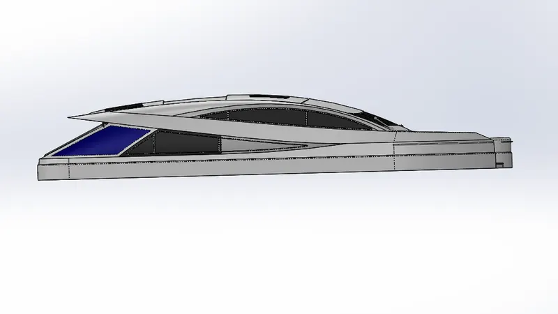
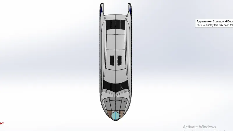
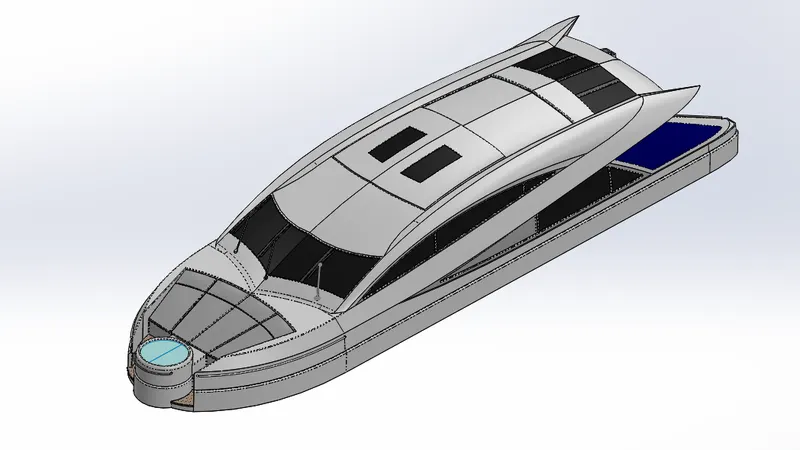
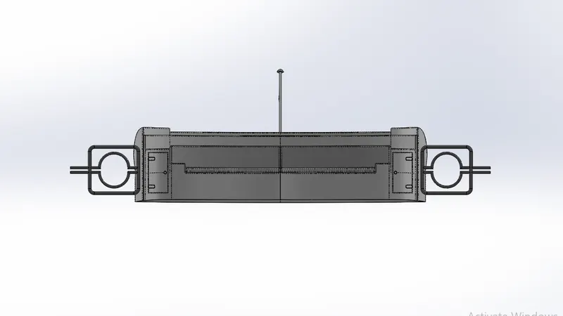
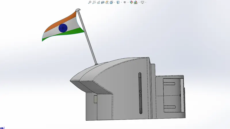
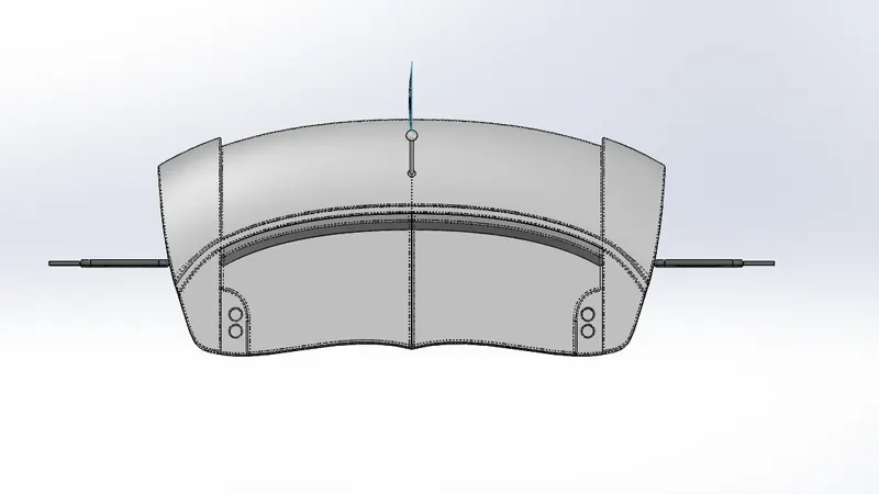
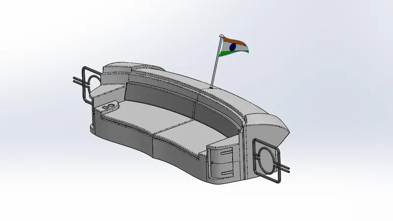
Superstructure is an upward extension of an existing structure above a baseline. It consists of the parts of the ship or yacht (in this case) that project above her main deck. The size of a watercraft's superstructure can have many implications in its performance, since these structures can alter their structural rigidity, their displacements, and/or stability. It encloses the cabin and living area of the yacht. They are designed in a manner, so that, they add value and hinder the speed and mobility in the least.
It was designed after importing the deck surface of the Hull as interface surface. Its designing required precise curvature during the sketching stage to avoid any bad geometry from showing up in the modelling stage.
Commands Used- Sketch, Offset Entities, Convert Entities, Extruded Surface, Swept Surface, Knit Surface, Fillet, Ruled Surface, Trim Surface, Project Curve, Lofted Surface, Filled Surface, 3D Sketch, Extend Surface, Delete Face, Extruded Boss, Extruded Cut, Offset Surface, Thicken Surface, Dome, Swept Boss, Split Line, Mirror.
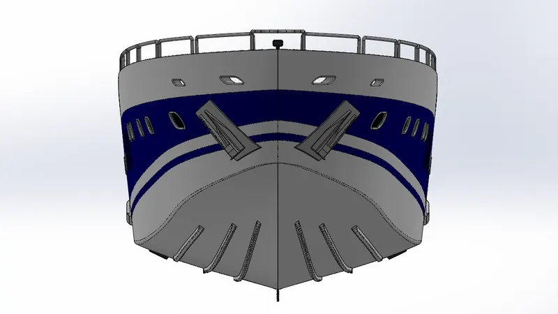
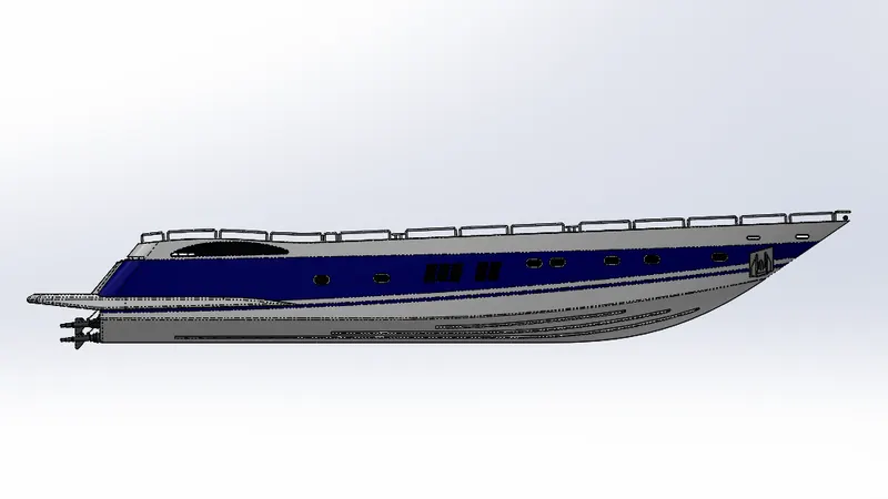
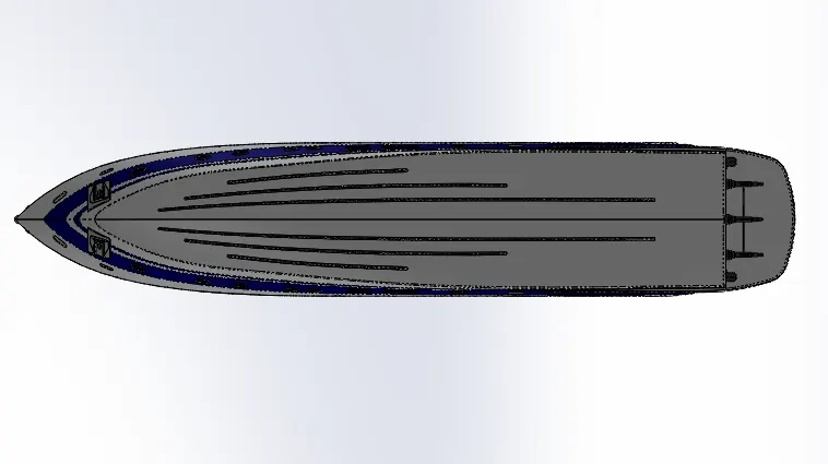
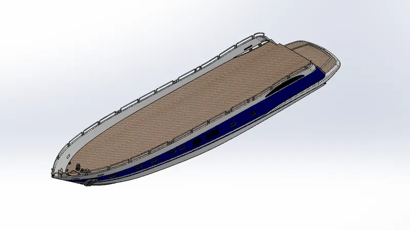
2.HULL
A hull is the watertight body of a ship or boat. The hull may open at the top or it may be fully or partially covered with a deck. A top the deck may be a deckhouse and other superstructures. The hull shape is chosen to strike a balance between cost, hydrostatic considerations (accommodation, load carrying and stability), hydrodynamics (speed, power requirements, and motion and behavior in a seaway) and special considerations for the ship's role.
The hull designing required precise curvature during the sketching stage to avoid any bad geometry from showing up in the modelling stage.
Commands Used- Sketch, Offset Entities, Project Curve, Lofted Surface, Trim Surface, Extruded Surface, Knit Surface, Filled Surface, Shell, Extruded Boss, Extruded Cut, Fillet, Chamfer, Swept Boss, Revolved Boss, Dome, Helix/Spiral, Linear Pattern, Delete Face, 3D Sketch, Mirror, Split Body, Split Line, Offset Surface.
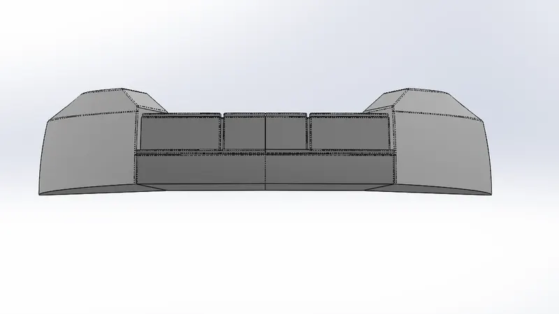
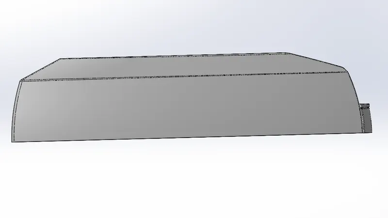
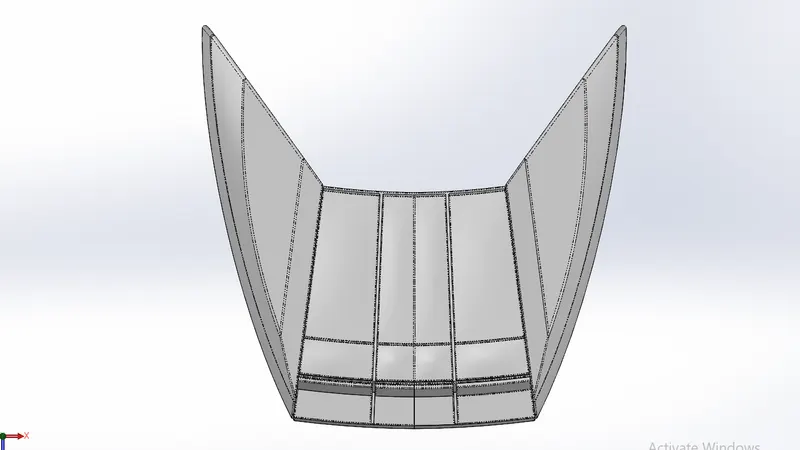
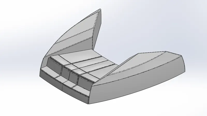
3.FRONT SEAT
Front seat was placed in front of the Superstructure on the hull. It was designed after importing the deck surface of the Hull as interface surface.
Commands Used- Sketch, Offset Entities, Swept Surface, Extruded Surface, Trim Surface, Filled Surface, Lofted Surface, Knit Surface, Chamfer, Revolved Boss, Extruded Cut, Mirror, Dome, Fillet.
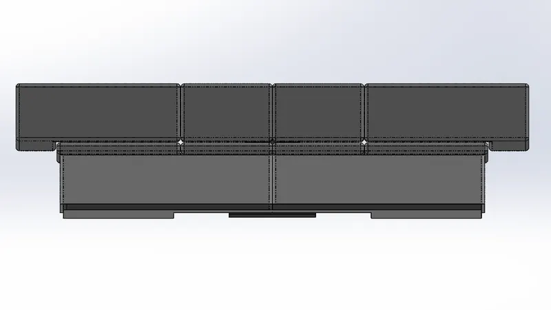
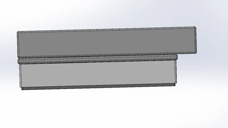
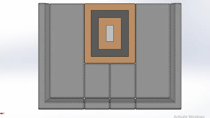
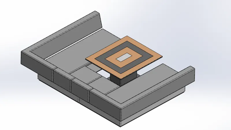
4.MIDDLE SEAT
Middle seat was placed in the shaded area closely behind the Superstructure backdoor. Unlike the Front and rear seats, the middle seat was designed using Soild Modelling commands.
It was designed after importing the deck surface of the Hull as interface surface.
Commands Used- Sketch, Offset Entities, Extruded Boss, Chamfer, Fillet, Mirror, Extruded Cut.
5.REAR SEAT
Rear seat was placed over the garage behind the Superstructure. It was designed after importing the deck surface of the Hull as interface surface.
Commands Used- Sketch, Offset Entities, Swept Surface, Offset Surface, Trim Surface, Ruled Surface, Knit Surface, Extend Surface, Extruded Surface, Lofted Surface, Extruded Boss, Extruded Cut, Chamfer, Fillet, Swept Boss, Mirror, Revolved Boss.
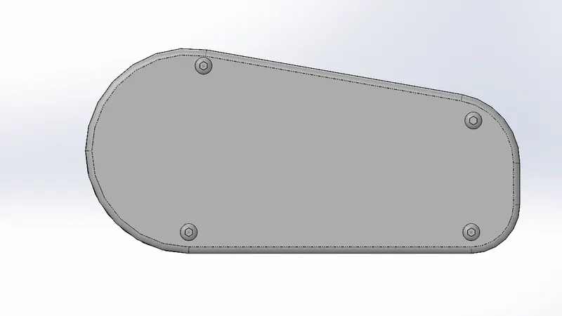
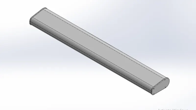
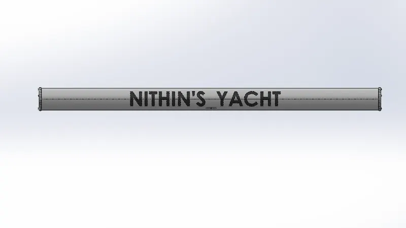
6.RADAR
Radar is used to detect other ships and land obstacles, to provide bearing and distance for collision avoidance and navigation at sea. They are electronic navigation instruments that use a rotating antenna to sweep a narrow beam of microwaves around the water surface surrounding the ship to the horizon, detecting targets by microwaves reflected from them, generating a picture of the ship's surroundings on a display screen. A Radar has a flat antenna that spins, emitting a signal, then listening back for that signal. The return signal bounces back at varying times based on what it may be bouncing off of.
Commands Used- Sketch, Offset Entities, Convert Entities, Extruded Boss, Fillet, Extruded Cut, Sketch Driven Pattern, Mirror, Split Line.
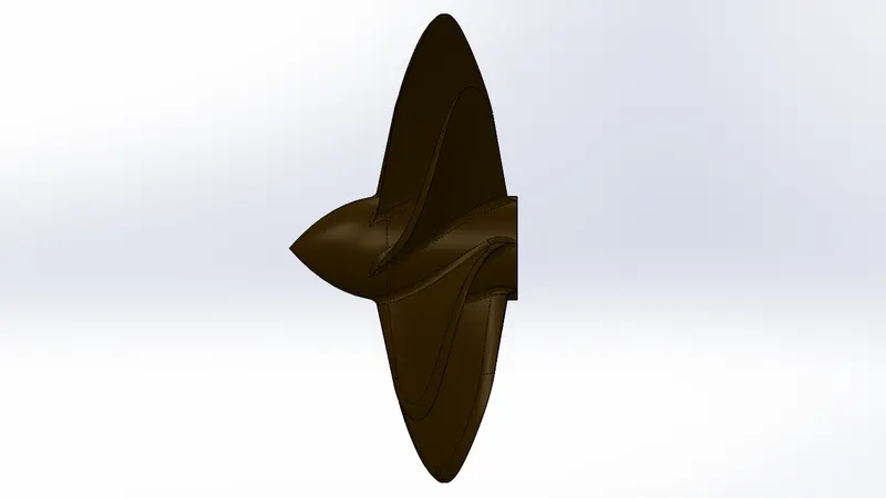
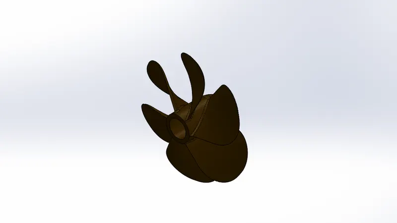
8.PROPPELLOR
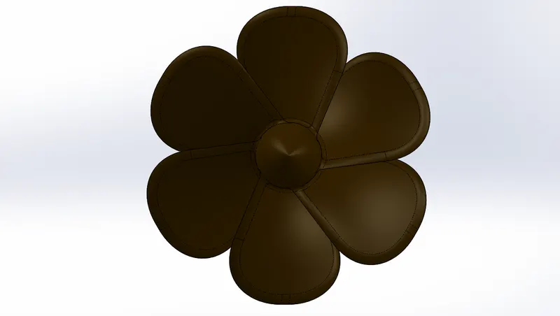
A propeller is a type of fan that transmits power by converting rotational motion into thrust. A pressure difference is produced between the forward and rear surfaces of the airfoil-shaped blades, and a fluid (water in this case) is accelerated by the pressure difference.Most marine propellers are screw propellers with helical blades rotating around an approximately horizontal axis or propeller shaft.
Commands Used- Sketch, Revolved Boss, Lofted Boss, Fillet, Extruded Cut, Circular Pattern.
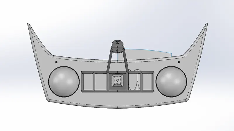
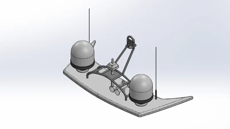
9.RADAR MAST
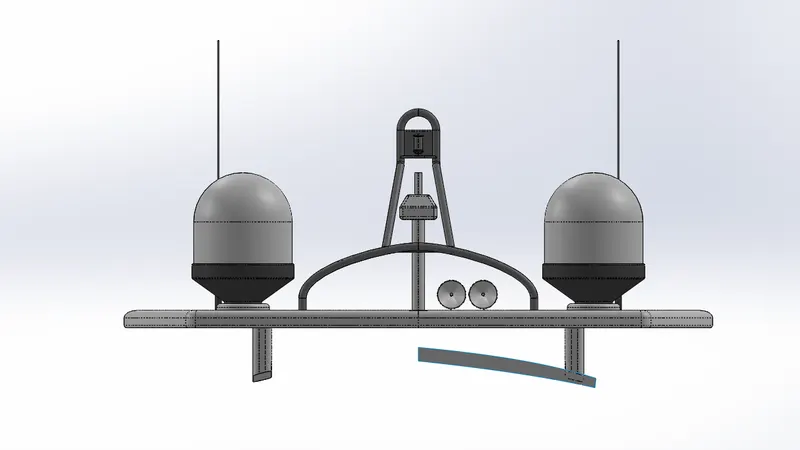
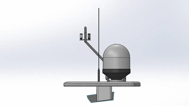
The Radar mast supports the radar, antennas, satellite domes and lights. It was designed after importing the top surface of the Superstructure as interface surface.
Commands Used- Sketch, Offset Entities, Extruded Boss, Fillet, Revolved Boss, Swept Boss, Mirror, Project Curve, Chamfer, Dome, Shell.
ASSEMBLY OF YACHT
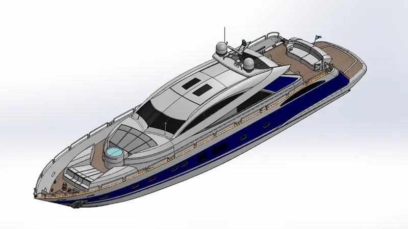
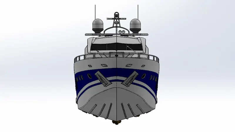
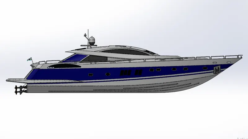
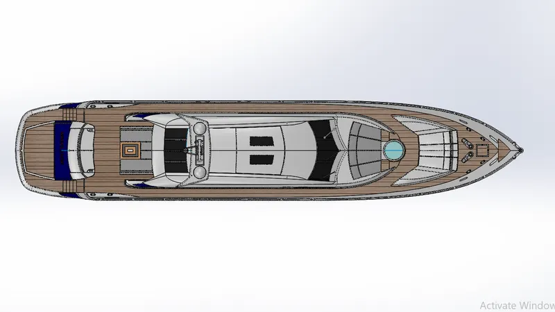
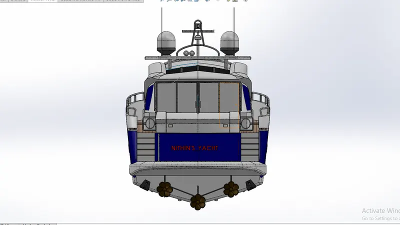
All the designed components are taken into the assembly section in Solid Works and using different mating features such as concentric, coincident, parallel, etc., the entire assembly of the yacht is created.
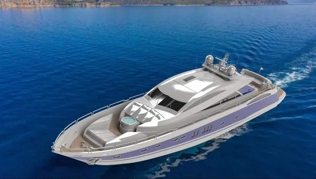
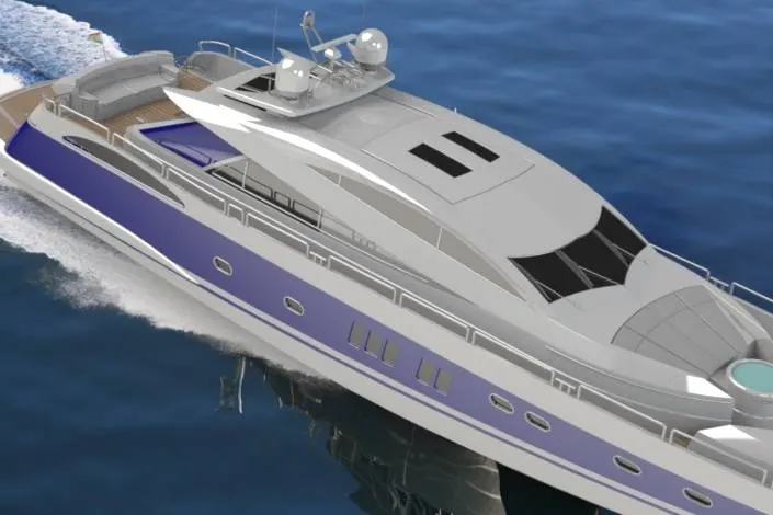
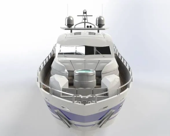
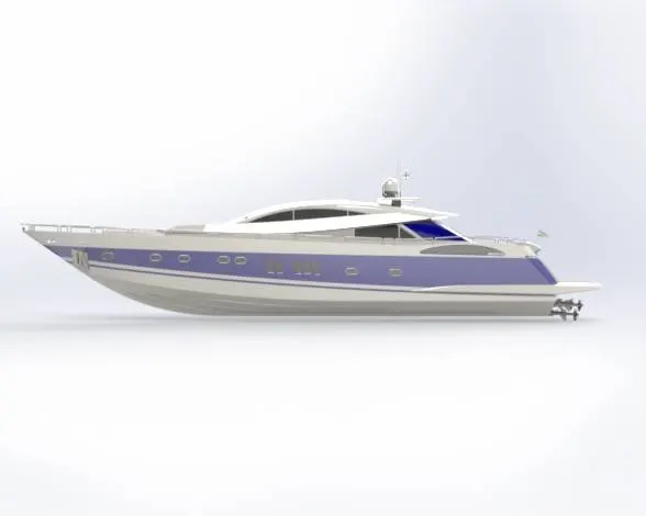
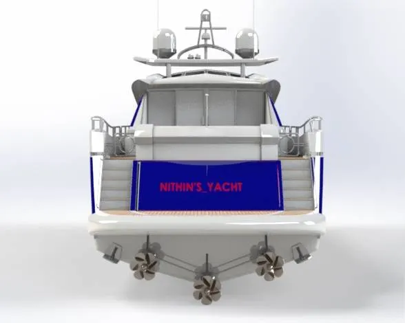
Once the application of the decals is finished, the assembled yacht is taken into Solid Works Visualize or using Photo-view 360. Here various aspects such as camera, external lightnings, background scenes, etc. are taken into consideration before the creation of the final rendering. The final rendered images of the luxury yacht are derived.
FEATURES USED TO ASSEMBLE YACHT
- Mates - Mates create geometric relationships between assembly components. As we add mates, we define the allowable directions of linear or rotational motion of the components. We can move a component within its degrees of freedom, visualizing the assembly's behavior.
- Insert Parts - We can insert the other components which need to be mated with the prime fixed component.
RENDERING :
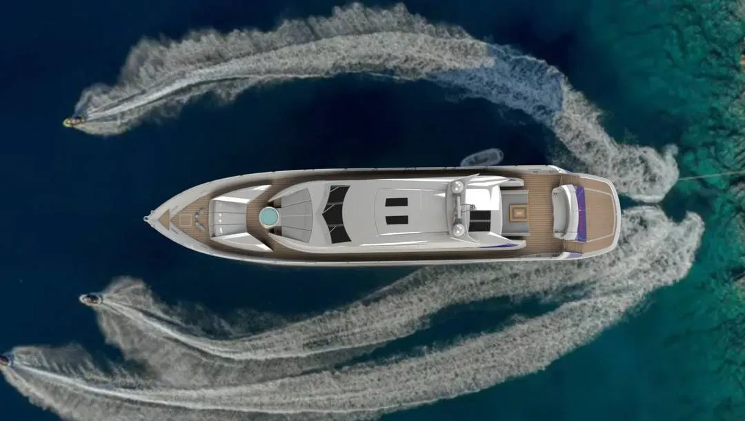
- Rendering is the process of creating realistic images of the photorealistic model with the environment.
- Rendering has been done in two ways in solid works. The following are the two ways,
- Photo view 360
- Solid-works Visualize
3.In the photo-realistic model some of the mate conditions and positions are changed to render realistic models.
4.Then the photo-realistic model is rendered into realistic images with different views.
5.Here I have used both the photo-view 360 and Visualise for rendering the assembled model.
CONCLUSION
- The parts of the yacht are sketched and modelled in the solidworks.
- The parts are inserted and assembled by giving proper mates in solidworks assembly.
- The realistic image was rendered in photoview 360 & solidworks visualize.