HYPERMESH_PROJECT 1 - MESHING THE INNER PANEL OF CAR'S SIDE DOOR
AIM :
To Mesh the given platic component and assign the variable thickness to different parts in the component.
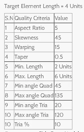
GIVEN QUALITY CRETIRIA :
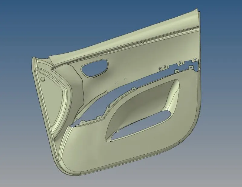
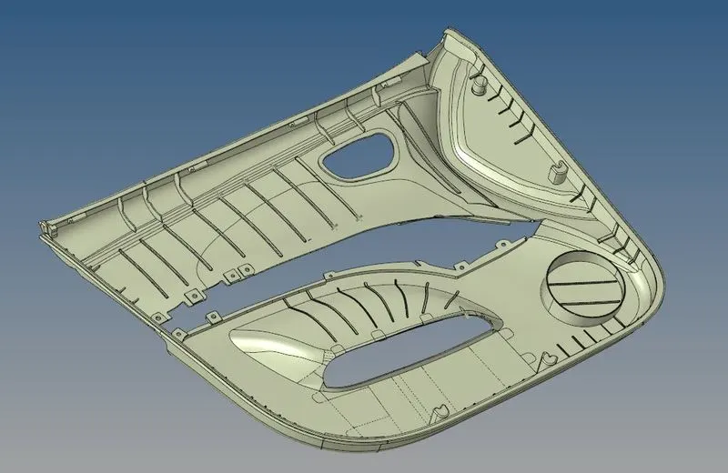
GIVEN COMPONENT :
PROCEDURE :
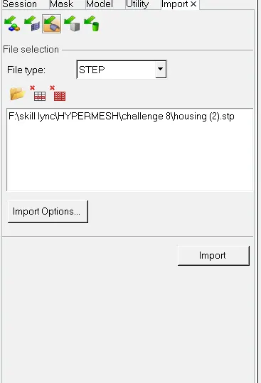
Step 1 : IMPORTING THE GEOMENTRY
Importing the geometry of the given model as HYPERMESH file by using the tool as import geometry.
STEP 2 : CHANGING THE MODE
- Change the color geometry mode from Auto to By Topo
- We select the By topo method because it is the handy option that is used to identify the free edges, shared edges, T-Junction, and Suppressed edge.Now, clean up the solid part If any present in the Geometry
- This also helps to find out the surface and solid in the components
STEP 3 : SPLIT THE COMPONENT
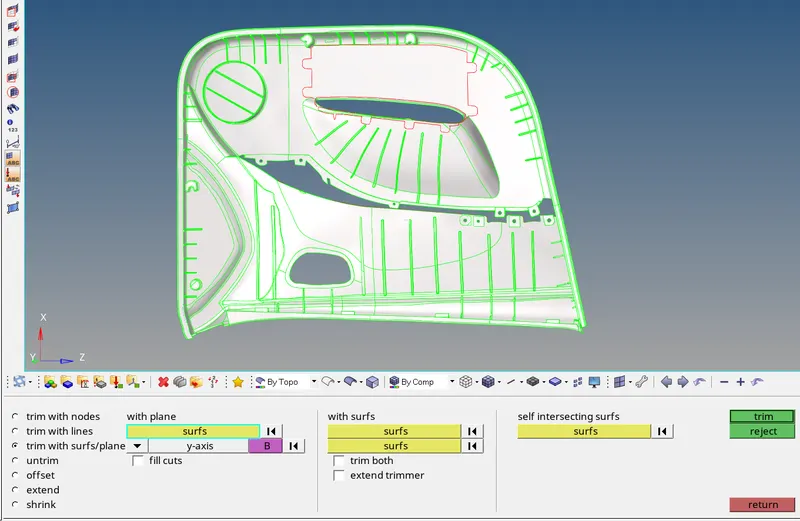
- To simplify the midsurface extraction we can split the main component into sub components
- In this i split the side door into 4 sub components
- For this process i use the TRIM WITH PLANE feature in the surface edit panel.
- Then select the whole component, and select the axis that i need to split
STEP 4 : SURFACE CLEANUP
- Always do the manual cleanup for the component.To do this press F11 or Go to Leanup Tools
- In this menu you can perform the various operations like Toggle, split, washer split, etc based on the cleanup require for the given component.

STEP 5 : MIDSURFACE EXTRACTION
- After spilitting the component, we need to extract the midsurface one by one by manual
- Before that, by using the organize command, assign the sub components into different collectors.
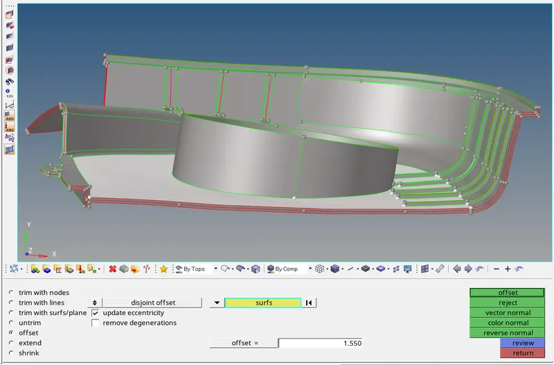
- For this midsurface, i use the OFFSET command.
- Before offset the suface, create the new collector for saving the midsurface for current component
- And make this collector as current component
- Now measure the distance between the two surfaces
- Then go to the OFFSET feature in the surface edit command
- Select the surface that you want to offset and make it as duplicate
- Reapeat the same process for all surface in the components
STEP 6 : CHECK THE CONNECTIVITY
- Before meshing process, always fix the connectivity issue between the surfaces that we offset
- We can solve the connectivity issue by using the EXTEND, TRIM WITH LINE, TRIM WITH SURFACE featues

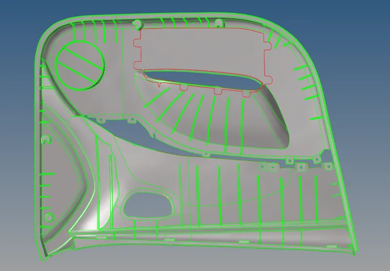
- And finally it looks like image that shown below
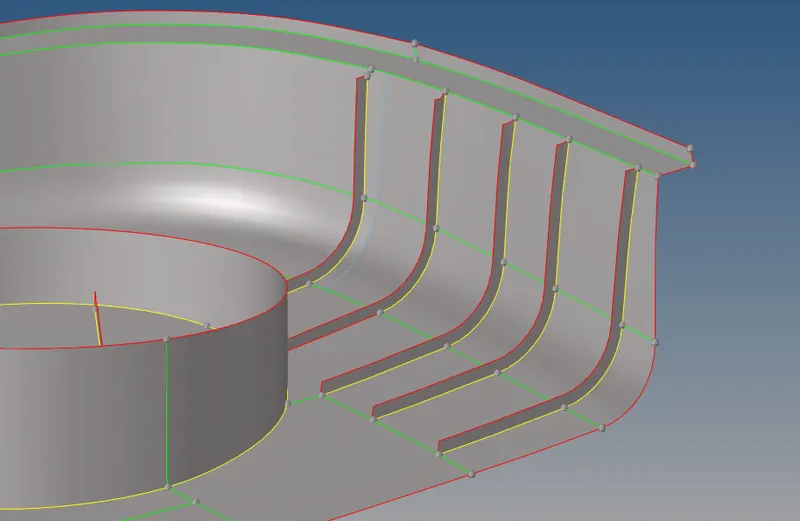
- In this yellow line indicates the intersection of three surfaces
- And green line indicates the intersection of two surfaces
- And red line indicates the free edges
STEP 7 : MESHING
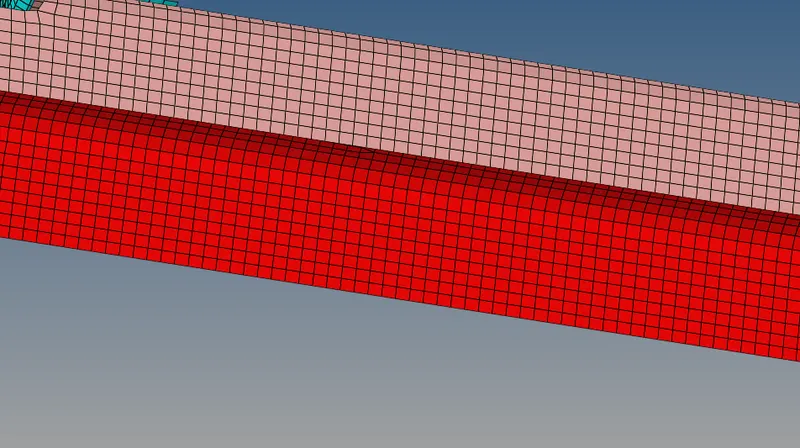
- Meshing is a part of the simulation process where complex geometries are divided into simple elements that can be used as discrete local approximations of the larger domain.
- The mesh influences the accuracy, convergence, and speed of the simulation.
- Click the F12 or select the automesh option in the geomentry menu.
- Automesh option is used for meshing a surface with 2D elements
- Change Geom mode as 2D in the Mainmenu bar
- Then select the Automesh option
STEP 8 : QUALITY MATCHUP
- clear the minimam and maximun length faiLng elements.
- Also clear the warpage, aspect, taper, etc
- For cleanup the element filing, use the QUALITY INDEX feature
- If any any element has failed, remesh it or use the replace option

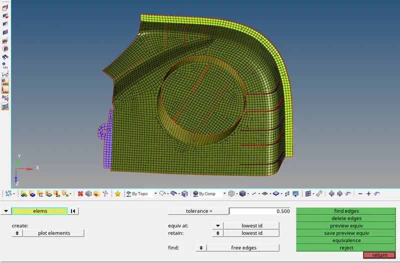
STEP 9 : CHECK THE FREE EDGES BETWEEN THE ELEMENT
- Afetr meshing, we have to check the edges between the elements
- If you have any edges inbetween the elemets, use the equilence option to fix this issue
- And we can also use the replace option
STEP 10 : ASSIGN THE THICKNESS
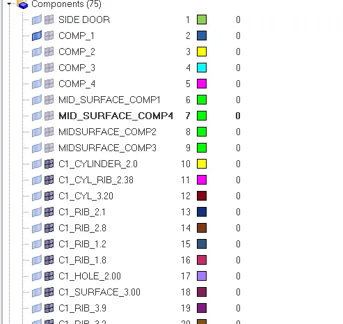
- Assign the different collector for different thickness
- Measure the thickness for individual surface
- Then create the property collector and assign the individual thickness
- And assign the property to the component collector
- And repeat the same process to all other surface in the component
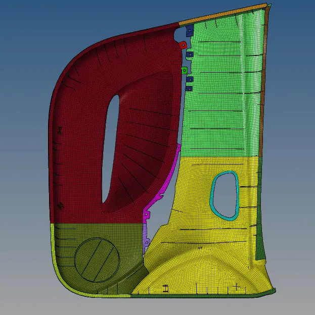
FINAL COMPONENT
RESULT :
Thus the given component is meshed under the given quality cretiria and assigned the thickeness for whole component.