ANSA - Meshing of Car Model
AIM :
Make a Detailed Report on the Meshing of the Car Model using a suitable target length
Geometry should be error-free
Explain about the meshing algorithm that has been used in this geometry
Also, explain about the quality criteria used in CFD
Off elements should be zero
Meshing is a technique used for software-based simulation for Finite Element Analysis (FEA) and Computational Fluid Dynamics (CFD). It is a very important process as the size and shape of the mesh directly impacts the accuracy of the solution.
Each element represents an individual solution for the differential equations applied to it. The results of which will help engineers create a 3D simulation of the component denoting the areas that will buckle under stress.
The geometry of mesh elements can be categorized into 1D, 2D, and 3D. The accuracy of the FEA model depends on the type of element chosen for simulation.
There are two different ways of creating a mesh-
- Structured (also known as Grids)
- Unstructured
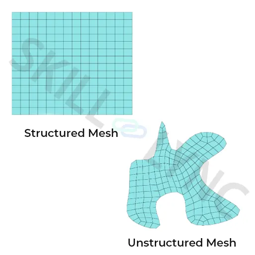
Meshing is an important step when it comes to performing an accurate simulation using FEA. It is a process of discretizing a CAD model into small elements.
PDEs are mathematical denotations of any physical system, and a few boundary conditions as well. The product behaviour in the actual world can be determined by calculations.
In that situation, techniques like FEA turn out to be a convenient method to demonstrate the complex behaviour of any product by capturing its physical phenomenon by the use of Partial Differential Equations (PDEs).
Generally, in Finite Element Analysis (FEA), the accuracy of results depends upon the fineness of the mesh.
Computational Fluid Dynamics
Computational Fluid Dynamics (CFD) is a branch of fluid mechanics that employs applied physics, mathematics, and analytical models. For CFD analysis we use computer software tools to visualize the movement of a gas or a liquid.
It's all about numerical flow simulations.
Importance of Meshing in CFD
Let’s explore the importance of meshing in CFD in brief:
- Experienced in solving the equations applied directly to the entire object. This happens due to the complexity or the irregularity of the shape. Meshing converts the irregular shape into more recognizable “elements”.
- It becomes easier for you to solve a partial differential equation allocated to a particular element. Solving these individual equations provides the solution for the complete geometry.
- It applies a numerical grid to the fluid body and its boundary revealing the ease and importance of meshing through Finite element simulations.
F
Types of Meshing and their Importance
There are two main types of meshes in
- Hybrid Meshing
- Sweep Meshing
Both these meshes use 3D elements
- Tetrahedral element meshing (Tet)
- When solving a complex structure, using a mix of meshes will reduce the computation time and increase the accuracy of the models.
- Hexahedral element meshing (Hex)
Hexahedral elements result in more accurate results with a lower number of element counts used than tetrahedral elements.
Hybrid Meshing
In mechanical engineering, you can prefer using a multizone method. It is a hybrid of hexahedral and tetrahedral elements. Hybrid meshing allows the user to create different parts of the geometry with different methods.
Sweep Meshing
It is useful for the user in spreading the mesh through the volume and faces of the structure, which in turn helps the user to create an efficient mesh with a regular size.
Deciding the type of mesh usually depends upon the level of accuracy based on the analysis type, whether explicit or implicit.
The importance of ANSYS in meshing is that it helps in reducing the amount of time, work and effort spent in order to get accurate results. Meshing generally consumes a significant amount of time to process simulation results. ANSA helps by providing a more reliable, better and more automated meshing tool, hence saving both time and effort.
Conclusion
The convergence, speed, and accuracy of a simulation are all affected by its mesh. The best possible mesh can be generated in Ansys with the help of the software's mesh generation tools.
meshing of the car :
initially check of the geometric errors :
-For the first step we will have to load the geometry once after loading we will have to check the errors if there is any major errors we will have to clear it out before meshing
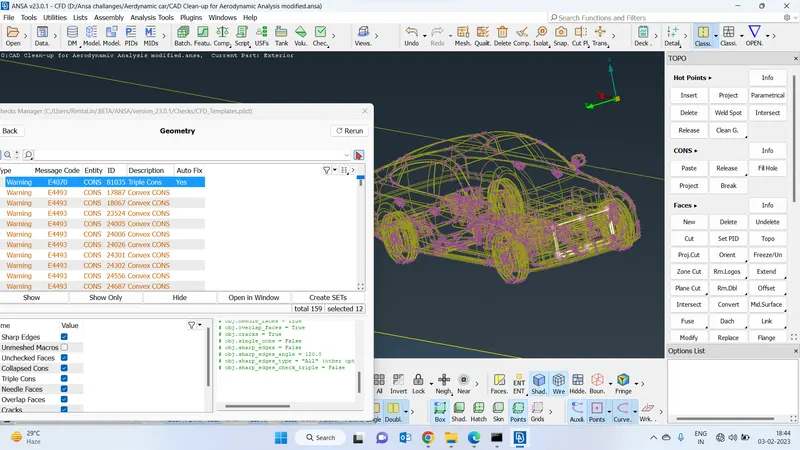
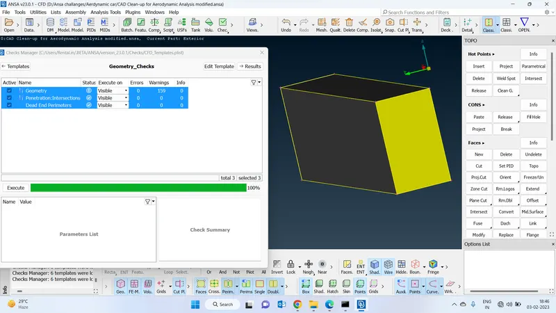
2 Check for geometrical errors :
-We can see there are no errors in the geometry
-So that we can proceed with further for meshing process
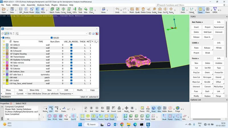
Assign the pids :
to provide a proper mesh component-wise and also to assign boundary conditions.
-To assign pids go to the pid section and create new pids and right click and select apply ans then select the components which you want to create pids
Grills :
Since the grills do not have big faces, we will have to provide a much less target length to do meshing.
So after analysing the geometry i went with 0.7 resolution
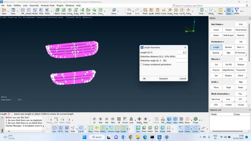
By using that target length all THE Curves have been captured properly:
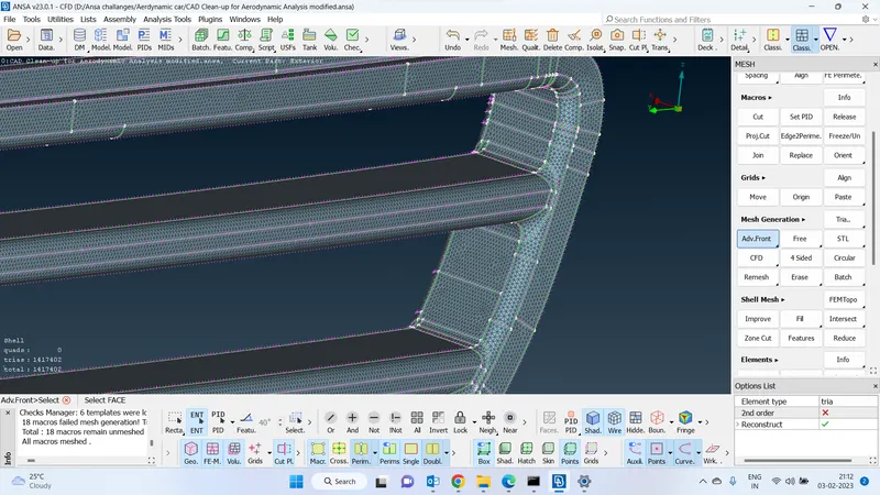
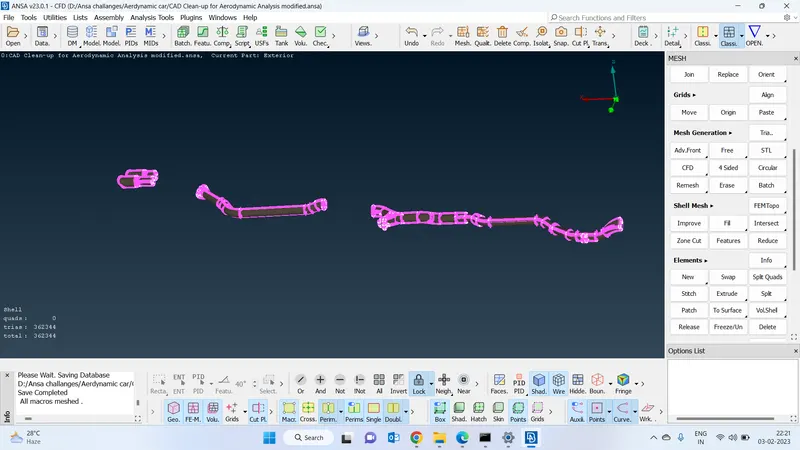
-provided advance front mesh algorithm
-This algorithm choose based on the geometry since it is providing uniform.
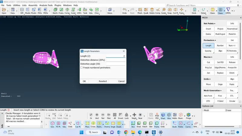
Mirror spacing :
-Based on the geometry we will have to provide the length and go for the geometry.
-2 is the length provided for this geometry based on the complexity. which is more than enough to capture the prooperties of the geometry while meshing
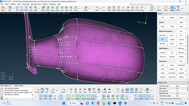
Used cfd meshing algorithm for side mirrors :
Used cfd mesh for better meshing.
-The algorithm has a feature to capture and create finer mesh where the curvatures are more
Exterior target length :
For the exterior part, the cfd target length has been provided based on the face size of the geometry
-Maximum length - 20
-Minimum length - 6
We do not need to provide a low minimum target length in this component since the faces are big
The provided target length is more than enough to capture the geometric features and according to that we can provide meshing algorithm
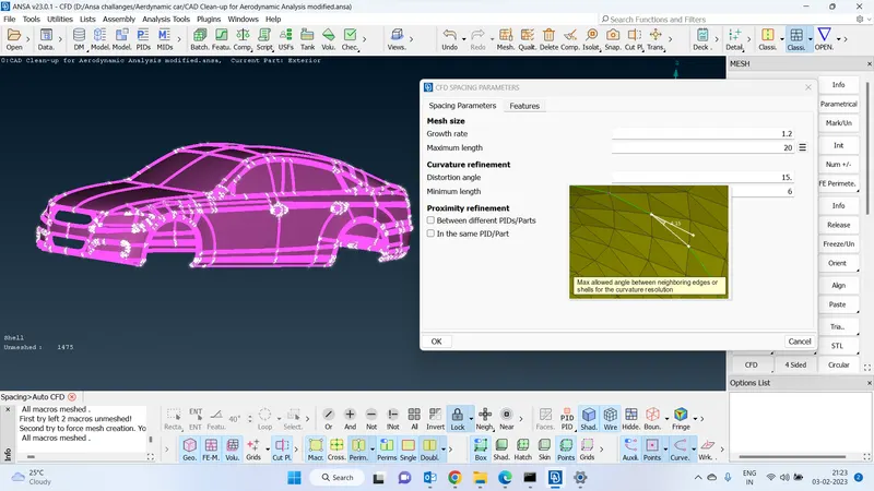
Auto CFD algorithm for exterior component
We have used the CFD algorithm for this geometry it will automatically make the mesh finer where the more bends in the geometry and it will create a normal mesh in the remaining areas.
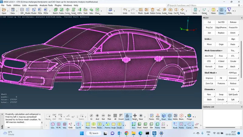
Froze all the 3 pids :
Freeze all the pids which we have meshed till now so that when we do the meshing for the remaining pids without effecting this one
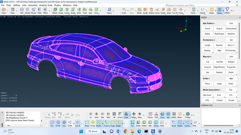
Bottom, engine, engine housing, transmission Target length :
The length that has been provided for the above-mentioned components is 10 which is more than enough to capture all the features while meshing is not more than enough than the geometric then the mesh will distorts.
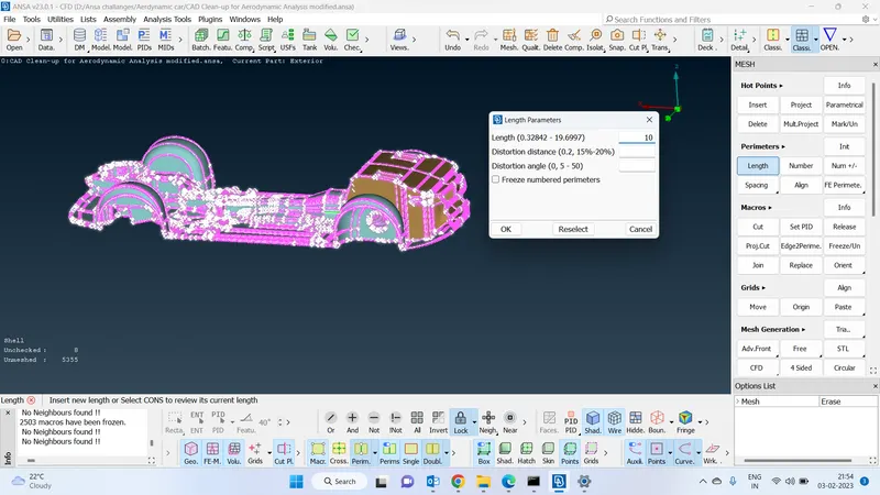
Target length :
The target length has been specified for the above geometry from a maximum of 10 to a minimum 4
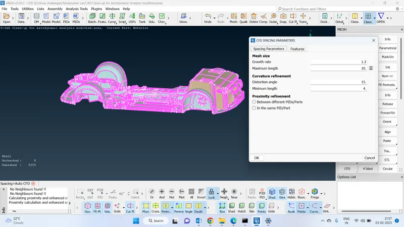
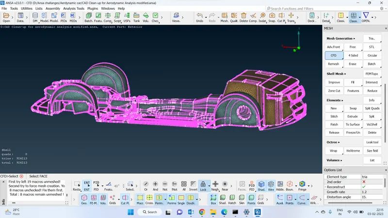
Advance cfd algorithm for the above components :
Fot these components we will have to choose cfd algorithm to capture the geometrical errors properly
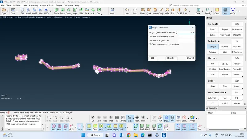
0.5 Target length for exhaust :
We have increased the resolution to 0.5 so that we can capture all the geometric properties properly
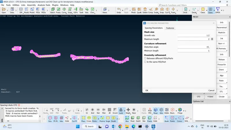
Spacing for exhaust :
Cfd parameters that have been provided a maximum length of 2 and the minimum length as 1
Auto cfd for exhaust :
Advance front meshing algorithm was choosen for this geometry since it will create an equal size of mesh throughout the geometry
-And also it is very useful to capture the geometric parameters
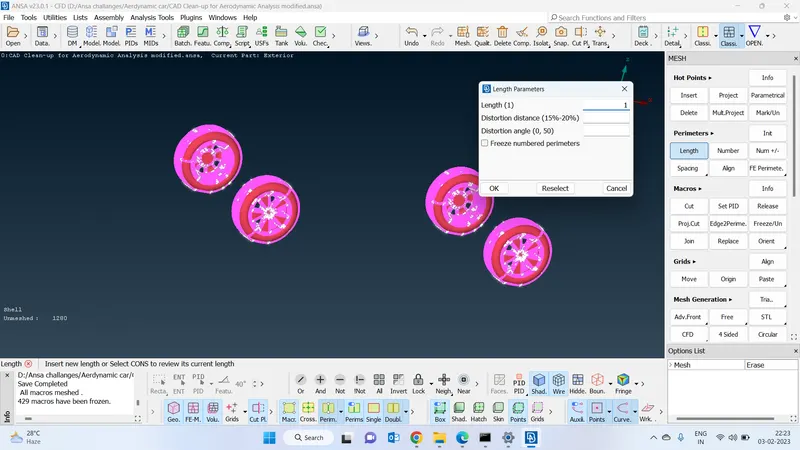
Wheel target length :
Increased the wheel resolution to 1 before specifying the target length to 1 so that it will become useful for to create a meshing to capture geometric features properly
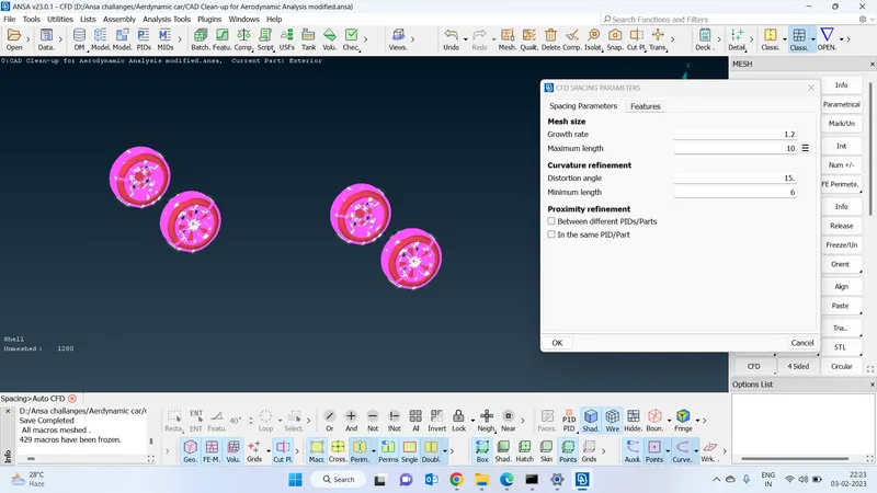
Wheel spacing :
cfd spacing for wheel
maximum length -10
minimum length - 6
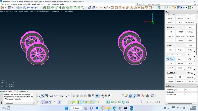
Use advanced front algorithm for wheels :
This is how the meshing has been generated based on the target length that we have provided
Radiator cfd parameters :
CFD parameters
Maximum length - 5
minimum length - 2
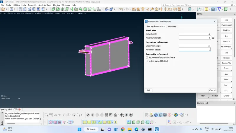
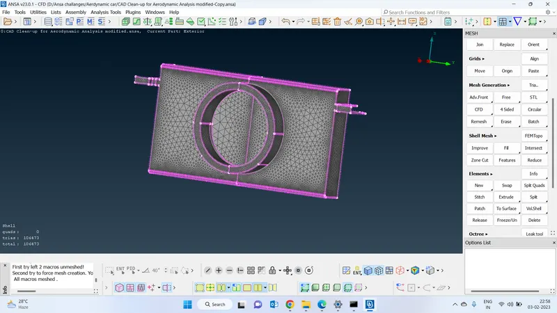
Radiator final mesh :
Used cfd meshing algorithm since the geometry has a big face so that it will aautomaticallycreate a mesh based on the target length
which will reduce the no of elements in the geometry
Wind tunnel cfd spacing :
CFD parameters for wind tunnel
Maximum length -200
minimum length -100
Sice the geometry has a flat faces we need not to go the finer mesh
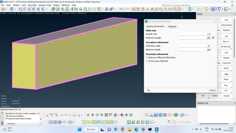
Wind tunnel cfd spacing :
Since the faces are flat we need not to go for the finer mesh
-Thats why i went with cfd algorithm it will automatically generate a mesh based on the complexity of the geometry it will increase or decrease the no of elements
Wind tunnel with advance front meshing algorithm :
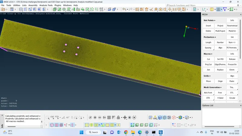
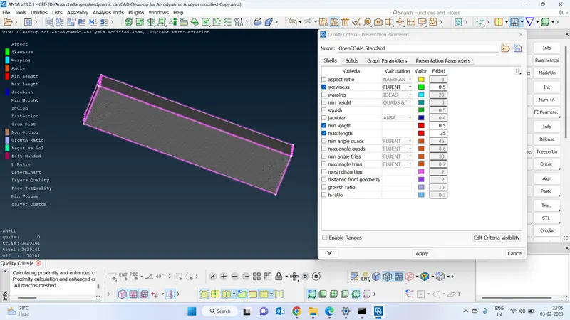
Quality criteria :
By clicking the function of hidden we can set the quality parameters
After reconstruct :
Enable only skewness ,maximum length ,minimum length.
Improve the quality of the mesh by reconstructing so that the off elements will reduce and increase the quality of the mesh
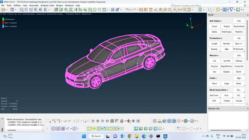
Final geometry :
This is how the final geometry looks like after meshing
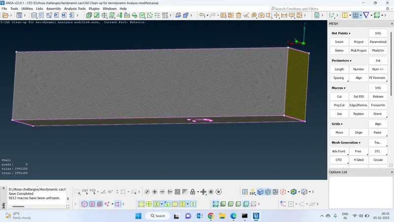
Google drive link to the meshing geometry :https://drive.google.com/file/d/1eZF682uIplR57Wbr8fkcCvRp3eGxAAyy/view?usp=share_link