Analysis of buckling phenomenon using FEA
Aim : to perform a buckling analysis on a cyclonic separator stand
objective: to find bucking factor of safety for cyclone seperator stand without support
to find the optimal position where the stiffener has to be placd for maximum bucking fator of safety
theory :
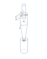
first import the Cyclone separator file into Solidworks. It gets imported as an assembly, so suppress all the parts except the stand. (shown as fig 1) In the analysis, buckling analysis is selected, then click on New study select buckling study Rename the study-Analysis without stiffnerthen Click ok. here 'Alloy steel' is applied as material to the stand,(material properties shown as below) bottom faces of the columns are fixed, by selecting fixture geometry the load of '150000N' is applied on the plate above the columns (In compressive direction), Default mesh is applied (shownas fig 2) and the analysis is solved.
material properties
| model type | linear elastic isotropic |
| material | Alloy steel |
| elastic modulus |
210000 N/mm^2 |
| possion ratio | 0.28 |
| shear modulus | 79000 N/mm^2 |
| mass density | 7700 kg/m^3 |
| tensile strength | 723.8256 N/mm^2 |
| yield strength | 620.422 N/mm^2 |
| thermal expansion coefficent | 1.3e-0.5 /k |
| thermal conductivity | 50 W/(m-k) |
From the cyclonic separator assembly,first Import the Cyclone separator file into Solidworks.the stand part is separately saved as part file, then open it t gets imported as an assembly, so suppress all the parts except the stand.then the stiffener is created in the stand using the sketch and extrude extrude 80mm, post which, place the extruded part with offset function to around 900mm(Downwards direction).
The sketch is extruded with an offset from the top plate of '1m' and thickness of '75mm'.
In the analysis, buckling analysis is selected, 'Alloy steel' is applied as material to the stand, bottom faces of the columns are fixed, by selecting fixture geometry the load of '150000 N' is applied on the plate above the columns (In compressive direction), Default mesh is applied (shown as fig 2)and the analysis is solved.
Case 3: Parametric study to determine the optimum position for the stiffener.R
After completion of case 2, the Same simulation results are employed for design analysis.
It is carried out to determine the effect of the position of the stiffener (75mm thickness) along the length of the column on the buckling factor of safety.
Such that, the optimum position of the stiffener that gives the buckling factor of safety greater than 25
Defined Parameters:
1. Variables :Offet Distance: The stiffener was movedd axially from 0.25m to 1.75m through an increment of 0.25m from the datum(Ground level).
2.Constraints :Buckling Factor of safety: The minimum buckling FOS criteria was set as 25
3.Goal : Maximize the buckling factor of safety parameter.
The above inputs were given to the solver. The output of the design study is shown below.
conclusion :
As we can see from the above table the maximum buckling factor of safety is obtained at the offset distance of the stiffener is 1m, which is equal to 27.75 From the analysis conducted in three cases, the stand without the stiffener showed a buckling factor of safety of 9.35. Whereas the one with stiffener exhibited almost 3 times the FOS that is 27.75. The stiffener location was found to be optimal using a parametric design study and the design met the requirements of buckling FOS greater than or equal to 25.