Analysis & Design of RCC shear walls in the model using ETABS
AIM & INTRODUCTIION :
AIM :
To design and analyse the RCC shear walls for a G+6 building with the size of 300x1500 at Grid A-11.
INTRODUCTION :
- In E-TABS the stuctural members such as beams, columns and slabs can be created and analysed its bending moment and shear force.
- We can Run the Concrete Frame Design fo the created structure to provide required both Longitudinal and shear reinforcement bars automatically.
- The values for the created structures can be automatically calculated by E-TABS.
- Here in E-TABS we can know the number of Reinforcement bars should be provided for the concrete structures.
- From Frame design analysis we can see both Top and Bottom reinforcem x 1ent figures for each beam sections.
- We can display concrete frame design result for Longitudinal and Shear reinforcement.
- And also for the Shear wall design such as Pier Longitudinal reinforcement, Pier Shear Reinforcemnt and Edge/Boundary Zone width.
- Moreover we can view the concrete beam design information as per IS 456:2000.
- The Design details of the overall structures can also be viewed as Summary, Flexural Details, Shear Details, Envelope.
PROCEDURE :
- Open E-TABS file for G+6 building which was attached with the Challenge 10.
- In that file we can see the G+6 building model with shear walls design.
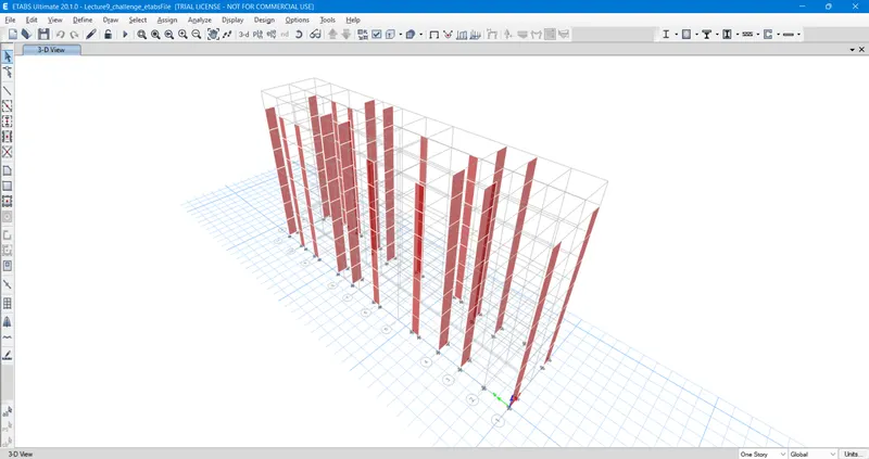
- After opening the file, we should able to see all the shear wall provided at all the floors from the top plan view.
- For that click Set Plan view tool at the toolbar above then select Terrace plan view and click APPLY.
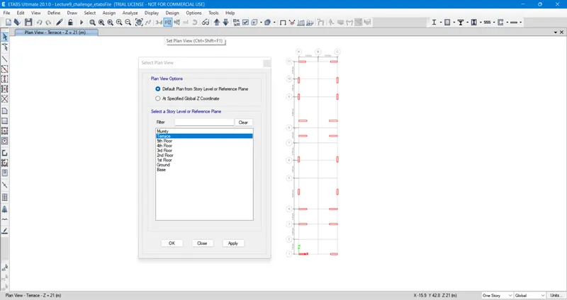
- Then to make sure that we can able to access shear walls at all the floors of the building model.
- For that select All stories option present at the Right Bottom Corner.
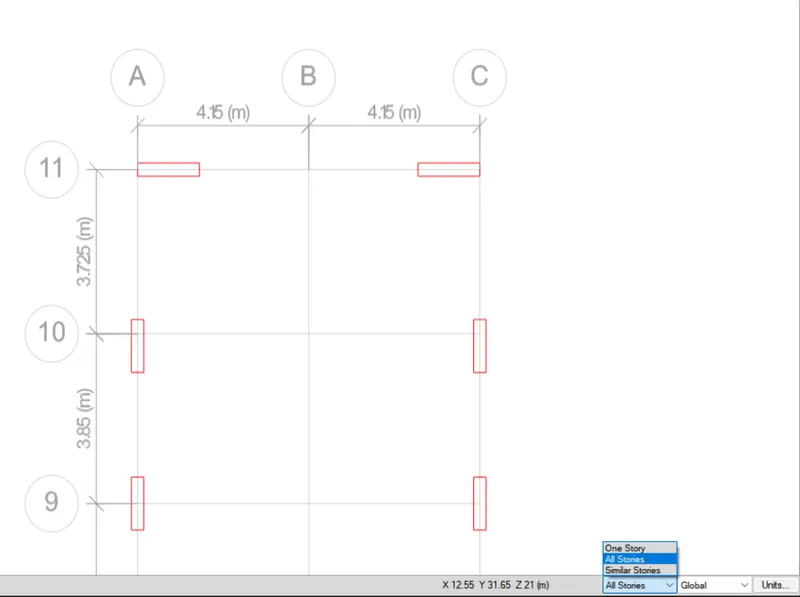
- Then select the shear wall at Grid A-11 with the Windows selection by mouse.
- Completing the Selection of the Specific shear wall, we can see that all the 7 shells of the building were selected and it can be seen at the Bottom Left Corner.
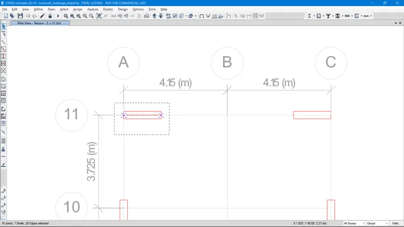
- After selecting the Grid A-11 shear wall at all the floors, Right click at the workspace and select Show selected Objects Only to show the selected shear wall only.
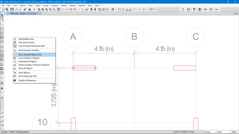
- Now we can see that only the selected shear is displaying on the workspace at the Terrace plan view.
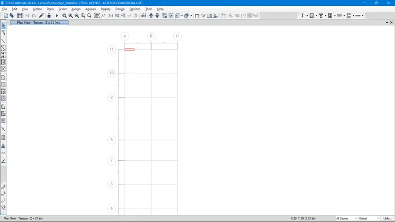
- To see the Elevation view of the showing shear wall at Grid A-11 click and select the Set Elevation View tool at the Tool bar above.
- Then the Tab will be opened below, from there select Elevation 11 and click APPLY.
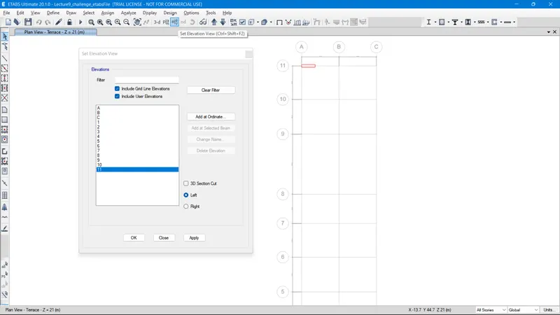
- Here we can see the Elevation view of the Shear walls at Grid A-11.
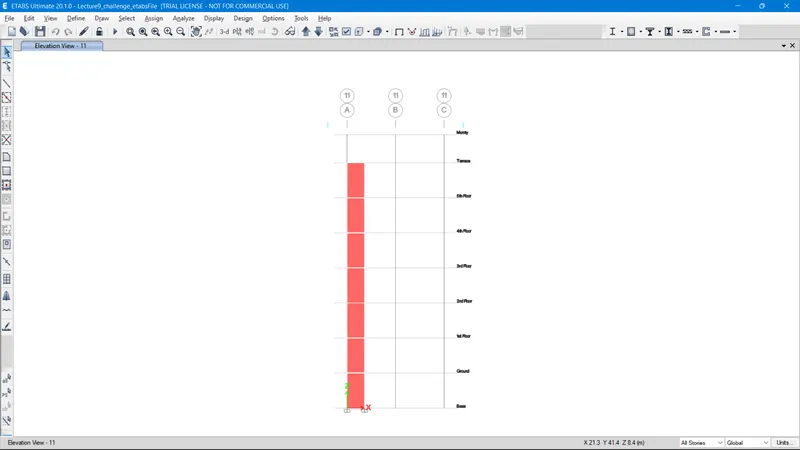
- To make sure that the Pier Label is applied at all the shear walss before.
- For that select Set Display Options tool at the Toolbar at the above workspace.
- Then Select the Labels check box under the Pier Assignments and click APPLY.
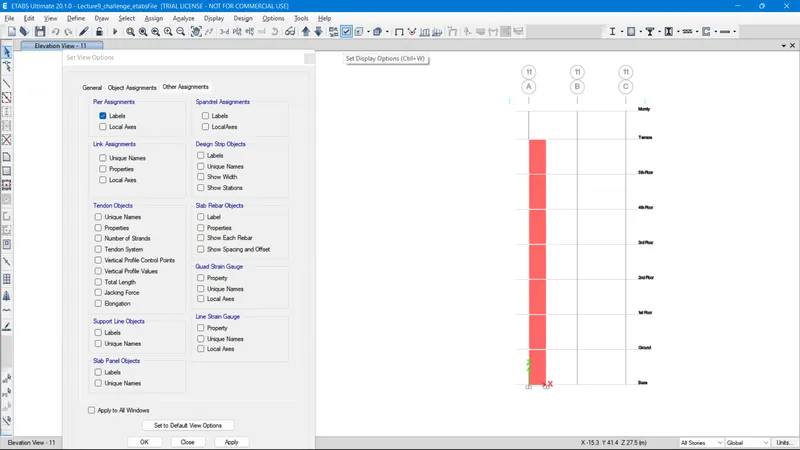
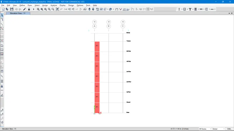
- Now we can see that the Pier Labels are assigned all over the shear walls as P1.
- Then the Shear wall can be analysed and it should be done by clicking the Run Analysis Tool at the Tool bar above.
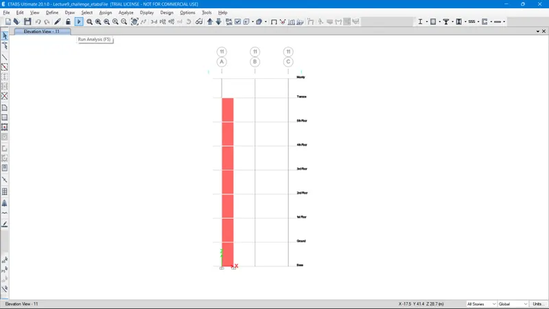
- While clicking the Run Analysis tool, it will ask to Save the file and we can save it at the required folder with appropriate name.
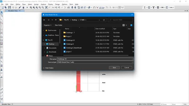
- After the analysis of the appropriate shear wall we can able to see the Reinforcement member requirement for Shear walls from base to terrace.
- To know that click the Shear wall Design tool present at the Top Right Corner of the toolbar.
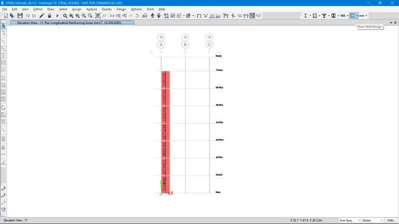
- After clicking the Shear wall design tool, we can see the Pier Longitudinal Reinforcement member requirement for the analysed shear wall.
- Followed by to know the other reinforcement members requirement for the shear wall.
- We have to select the Display design information to see the various Display shear wall design results.
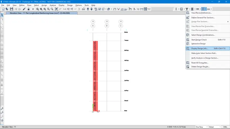
- Then to see the Pier Shear Reinforcement member requirement click and dropdown the arrow next to the Shear Wall design.
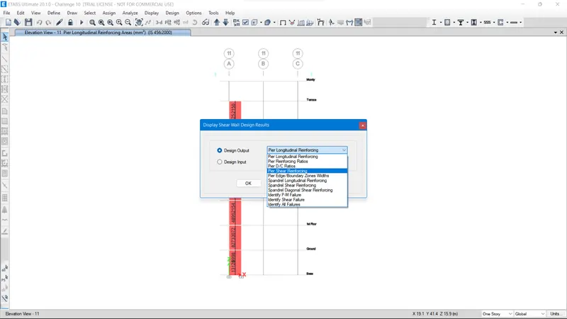
- After selecting the Display Design Information, the Display shear wall design Result Tab will be opened.
- From the opened Tab, Select Pier shear Reinforcement by dropping down the options of Design Output.
- Now we can see the results of the Pier shear reinforcement at the elevation view of the shear wall.
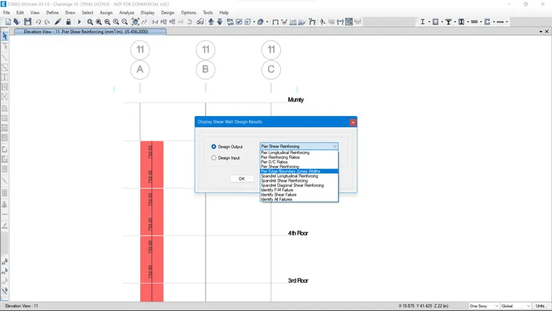
- Likewise to see the Pier Edge/Boundary Zones Width member requirement click and dropdown the arrow next to the Shear Wall design.
- After selecting the Display Design Information, the Display shear wall design Result Tab will be opened.
- From the opened Tab, Select Pier Edge/Boundary Zones Width by dropping down the options of Design Output.
- Now we can see the results of the Pier Edge/Boundary Zones Width at the elevation view of the shear wall.
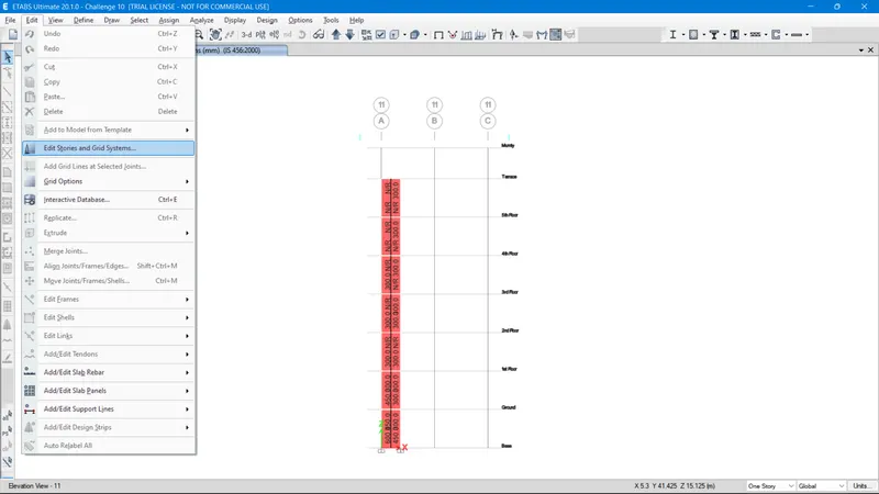
- At last check the Stories and grids assigned to the given building model of G+6.
- For that click Edit < Edit stories and Grid System to open Edit Story and Grid System Data Tab.
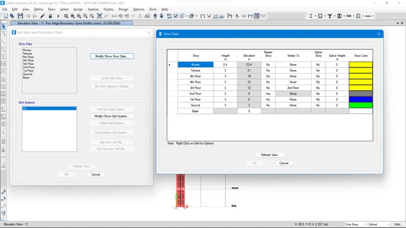
- After opening of the Edit story and Grid system Tab, select Modify/Show Story Data option at the Right.
- Then the Story Data Tab will be opened, there we can see the Total number of stories from Base to Terrace with the heights assigned.
RESULT :
A. ) Extract values of longitudinal steel ratio, boundary element length and shear reinforcing ratio from the design results.
1. VERTICAL/LONGITUDINAL REINFORCEMENT OF SHEAR WALL AT GRID-11 A FROM ETABS (300 X 1500) :
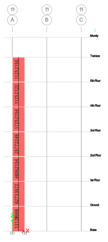
2. HORIZONTAL/SHEAR REINFORCEMENT OF SHEAR WALL AT GRID-11 A FROM ETABS (300 X 1500) :
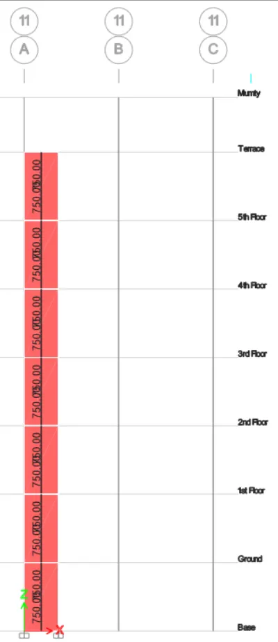
3. BOUNDARY ELEMENT WIDTHS OF SHEAR WALL AT GRID-11 A FROM ETABS (300 X 1500) :
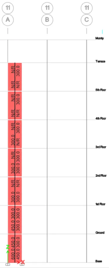
DETAILING GUIDELINE FOR SHEAR WALL :
1. Minimum reinforcement of shrinkage and temperature.
2. Ultimate limit state design rebar requirement. ----- Whichever is greater, should be drawn in RC shear wall detailing.
3. Ductility rebar requirement.
- Classification of shear wall as per IS-13920-2016 clause 10.1.4
- Slender wall `h_w/L_w = 21000/1500 = 14>2`
- Minimum net vertical reinforcement as per IS-13920-2016 Table-1 (iii)
- `2363 mm^2 = 0.0025 + 0.01375 (300/1500)`
- Minimum vertical reinforcement within boundary element Table-1 (iii)
- `1440 mm^2` on left (600mm width boundary element)
- `1080 mm^2` on right (450mm width boundary element)
- Minimum Horizontal reinforcement in shear wall as per IS-13920-2016 Table-1 (iii)
- `(rho_h)_min = 0.0025 + 0.5 [h_w /L_w -2] (rho_h - 0.0025)`
- `(rho_h) = 750/(300x1000) = 0.0025 , h_w = 21000, L_w = 1500`
- `(rho_h)_min = 0.0025 + 0.5 [21/15 -2] (0)`
- `(rho_h)_min` = 0.0025 which is the same 750 mm^2/m
- Maximum diameter of the rebar for shear wall as per IS-13920-2016 clause 10.1.8
- `1/10` of wall thickness = `300/10` = 30mm
- Commercial rebar diameter 25mm shall be adopted.
- Confining reinforcement spacing for boundary element as per IS-13920-2016 clause 10.4.4
(i) `1/3` of minimum member dimension = `300/3` = 100mm
(ii) 6 times smallest main rebar = 6x25 = 150 mm
(iii) 150 mm permissible if verticle bars are spaced at maximum 200mm
Maximum spacing of confining reinforcement in boundary element 150mm
- Confining reinforcement within boundary element as per IS-13920-2016 clause 10.4.4
`A_s__h = 0.05 S_v h f_ck/f_y`
`S_v` = 150mm, h = 1000 mm
`A_s__h = 452 mm^2`
B. ) Provide cross sectional steel arrangement of the shear wall from its base up to terrace, in compliance with provisions of IS 13920 – 2016. AutoCAD application can be used for this exercise. Alternatively, it can be drawn by hand as well.
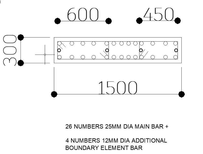
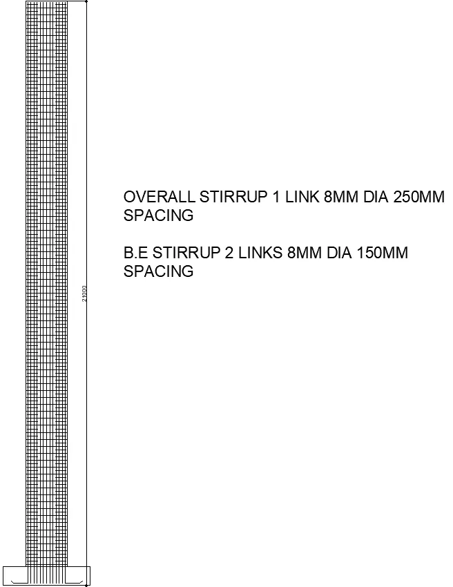
C. ) Provide elevation drawings of the reinforcement details of the shear wall from base up to terrace.
1. STOREY ASSIGNMENT TAB TO REFER ELEVATION OF SHEAR WALL :
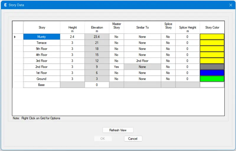
2. ELEVATION DRAWING OF THE REINFORCEMENT DETAILS OF THE SHEAR WALL FROM BASE UPTO TERRACE :