Analysis & Design of RCC shear walls in the model using ETABS
Aim:- to provide the following the details of the shear wall for the G+6 building given
- longitudinal steel ratio
- boundary element length
- shear reinforcing ratio
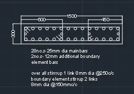
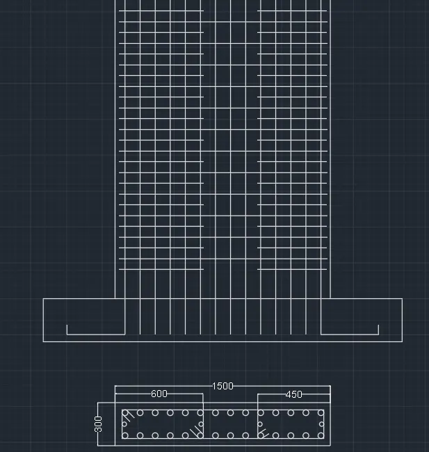
- sketch the reinforcing details of the shear wall and its cross section
To analyse and design shear wall @A11 (size of the shear wall is given as 300 x 1500)
- download the attachment provided and open in E-tabs
- then check for the assignments
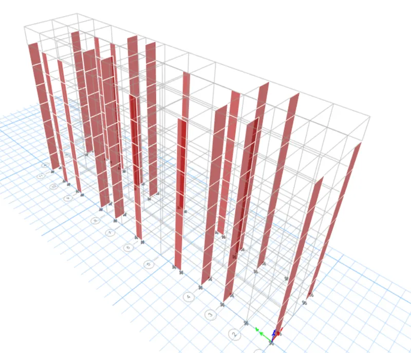
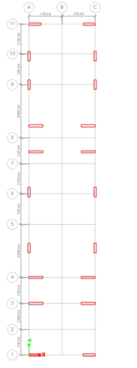
- go to run analysis
- after completing the analysis go to design
- click on the design shear wall

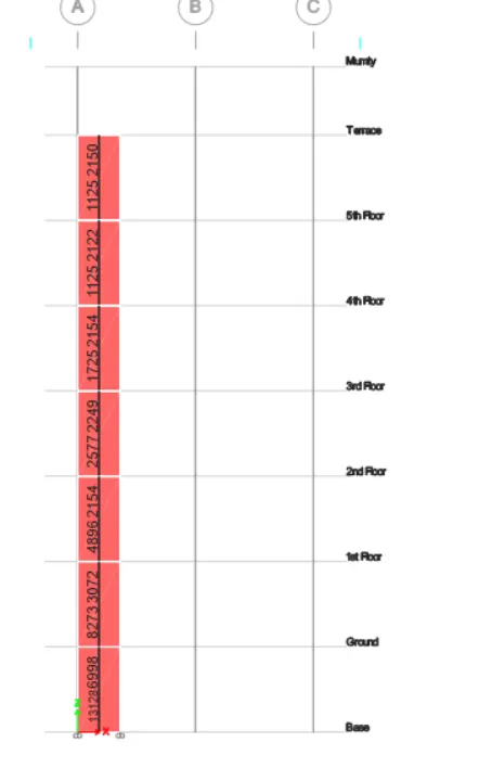
- after analysis and design has been completed we can view the reinforcing details of the shear wall
- to view the details of the particular shear wall @A11
- select the shear wall
- click on the show selected objects only
- go to elevation to view the details from base to terrace
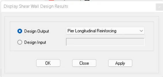
LONGITUDINAL REINFOCING DETAILS OF THE SHEAR WALL
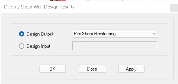
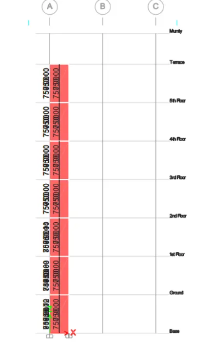
SHEAR REINFORCING DETAILS OF THE SHEAR WALL
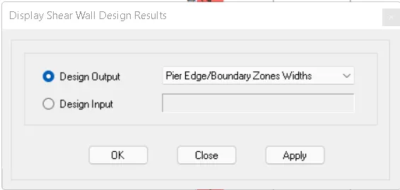
BOUNDARY ZONE WIDTH DETAILS OF THE SHEAR WALL
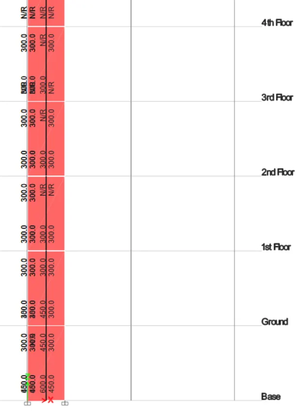
elevation details of the building
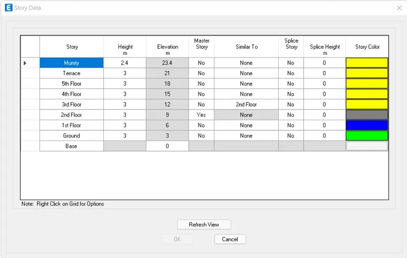
IS code provisions for the detailing of shear wall
- reinforcement requirement is taken as max of following
minimum reinforcement for shrinkage and temperature
ultimate limit state design rebar requirement
ductility rebar requirement
- classification of shear wall as per IS 13920-2016 clause 10.1.4
Hw/Lw=21000/1500=14
- minimum net vertical reinforcement as per IS 13920-2016
=0.0025+0.01375(300/1500)=2363mm^2
- minimum horizontal reinforcement in shear wall

=750/(300x1000)=0.0025
0.0025+0.5(21/15-2)=0.0025
- max diameter of the rebar for shear wall
1/10 of wall thickness==300/10=30
- confining reinforcement spacing for boundary elements
1/3 of the smaller dimension of the member
6 times the dia of the rebar
150mm permissible if vertical bars are spaced at 200mm
- confining reinforcement details within boundary element as per IS 13920-2016
0.05 Sv h (fck/fy)
RESULTS:-
- longitudinal and shearreinfocement are provided as per the obtained values from etabs
- boundary width is obtained as 600mm on the left and 450mm on the right
- the above mentioned shear wall is classified as SLENDER WALL
- max spacing of confining reinforcement is obtained as 150mm
- max dia of the reinforcing bar is obtained as 25mm
CROSS SECTION DETAILS OF THE SHEAR WALL