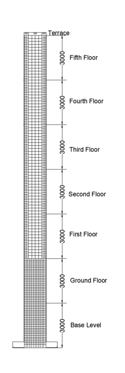
Analysis & Design of RCC shear walls in the model using ETABS
AIM:
This challenge aims to run the analysis and design of the RCC shear walls. And to extract the values of the longitudinal steel ratio, boundary element length and the shear reinforcement ratio from the design results.
PROCEDURE:
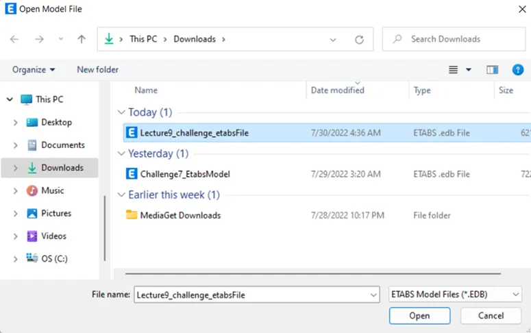
So first of all open the ETABS file which is given in the question itself. Open that file into the ETABS software on which we are going to work for designing the shear walls.
After opening the given file in the ETABS software with the appropriate location just as shown in the below given image:
Below is the given model in which we are going to work:
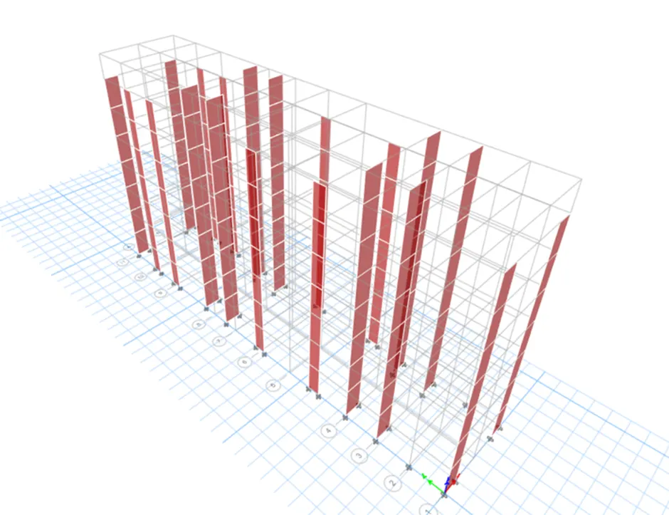
After opening the file the very first step that we are going to do is Run Analysis.
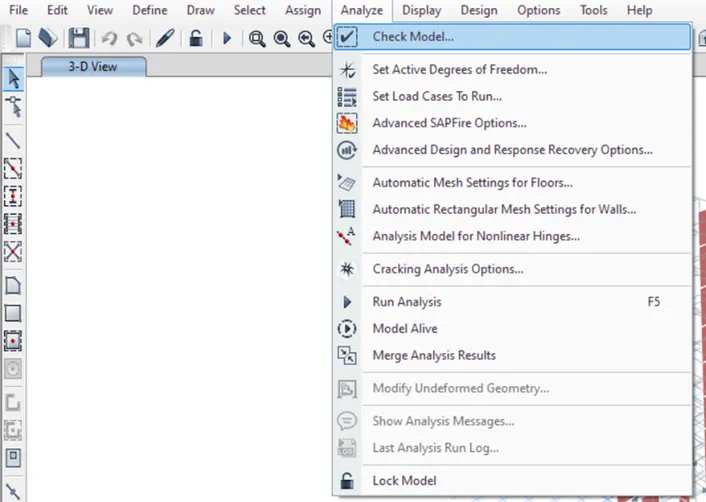
But before doing the Run analysis first, we have to check the model for any structural defects.
To check the model for any structural defect we need to go to the Analysis tab there will be a drop-down list and in that list, there will be an option called Check model just click on that option as shown in the below given image below:
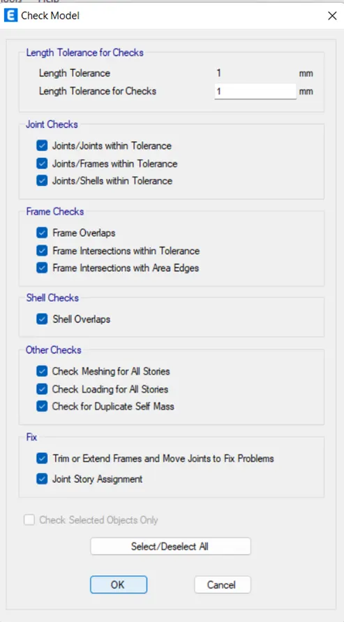
After this, a new dialogue box opens named Check Models in that dialogue box select all the options which are present in that dialogue box and then click OK and run the check just as shown in the below given image below:
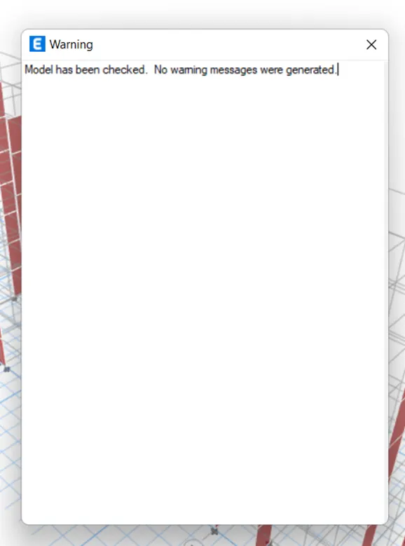
So the check has been done and there are no warnings shown in the below image. And it also means that we can proceed further with the analysis of this G+6 building.
After checking the structure we will adjust the view settings.
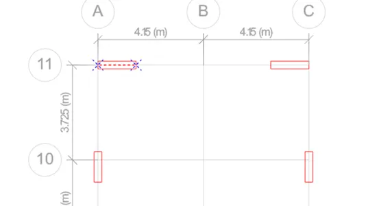
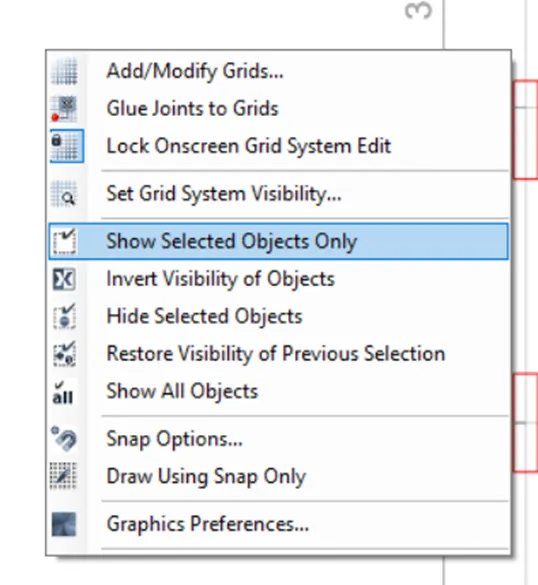
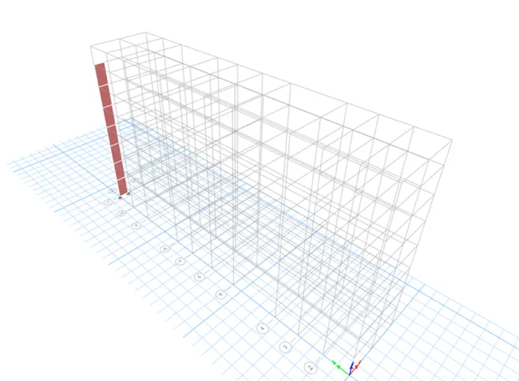
To adjust the view settings first we need to select the shear wall that we are expected to design and analyse after selecting the shear walls, right-click anywhere on the screen and then there will be a drop-down list in that list choose the option called show selected object only just as shown in the below given image:
Selected Shear Wall:
Right-click anywhere on the screen:
In 3D view selected Shear Wall:
So now after adjusting the view settings, we will have to make sure that the codes that we are using in design are correct or not.
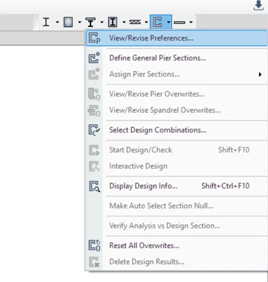
To do that, just go to the shear wall design icon and click on that icon after clicking on that icon a drop-down list appears on the screen from that list click on the option View/Revise Reference option just as shown in the below given image:
After clicking on that option a new dialogue box appears on the screen named Shear Wall Design Preferences for IS 456:2000 just as shown in the below given image below:
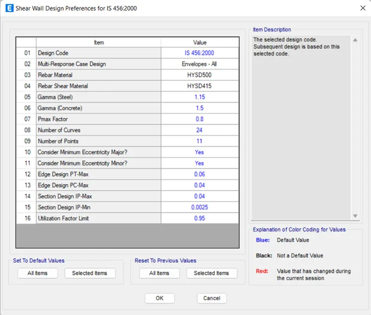
In that dialogue box make sure that the desired codes are selected based on the country/region where the project is located.
After making sure that the codes that are selected are corrected, now we can perform the Run analysis.
To do so just click on the Shear Wall Design icon which is present at the top-right corner of the screen as shown in the below given image:
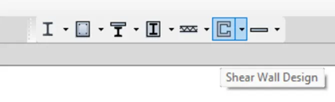
Now click on that icon, after clicking that icon the software starts checking the design just as shown in the below given image below:
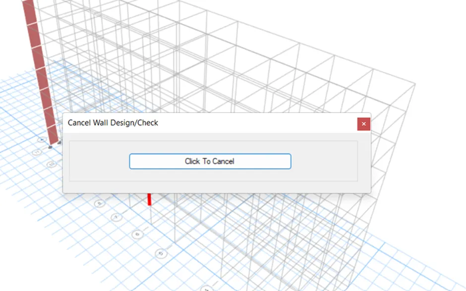
Now that the designing process has been finished in the ETABS software, we need to collect the all required data which will be helpful in further detailing calculations.
So to design the shear walls we need three main data:
Longitudinal Reinforcement.
Shear Reinforcement.
Boundary Element Width (BE).
And all these above data can be extracted from the ETABS software itself.
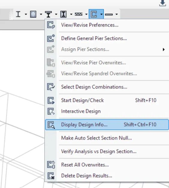
To extract these values from the ETABS software, simply go to the option Shear Wall Design and then there will be a drop-down list from that list choose the option Display Design Info and click on that option just as shown in the below given image below:
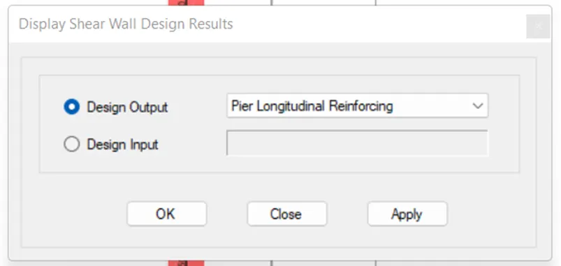
After this, a new dialogue box opens named Display Shear Wall Design Results, that dialogue box changes the design Output To Longitudinal Reinforcing just as shown in the below given image below:
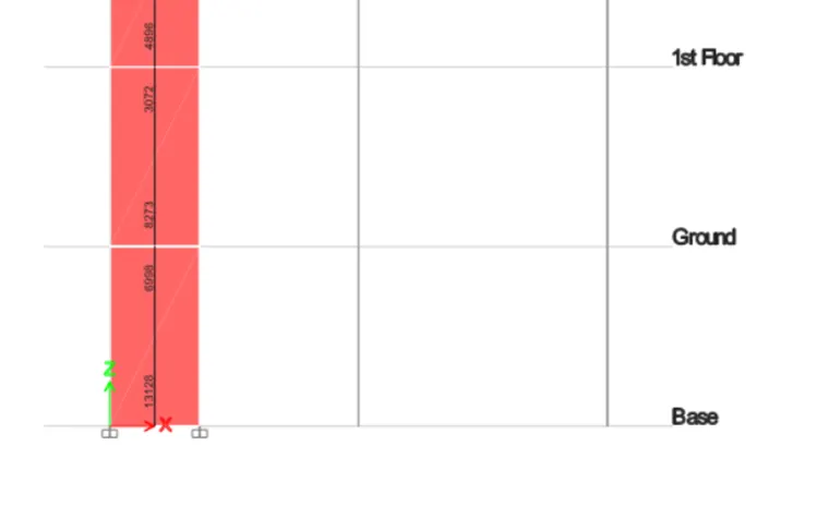
Maximum Longitudinal Reinforcement at the base:
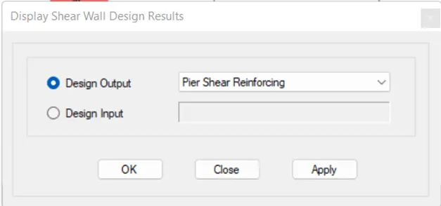
Now the same dialogue box opens named Display Shear Wall Design Results, in that dialogue box again change the design Output To Shear Reinforcing just as shown in the below given image below:
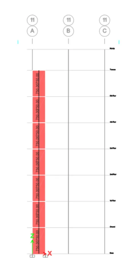
Shear Demand throughout the wall height:
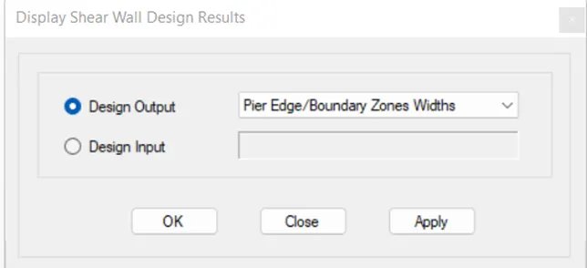
Now the same dialogue box opens named Display Shear Wall Design Results, in that dialogue box again change the design Output To Edge/Boundary Zones Widths just as shown in the below given image below:
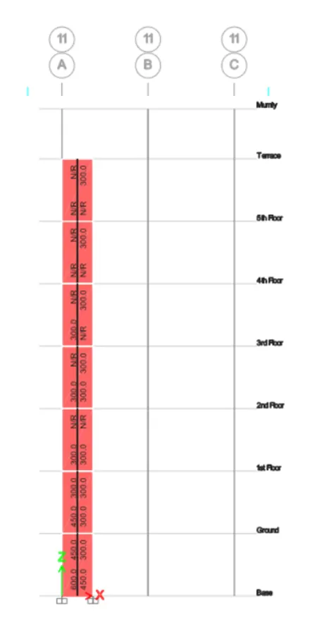
Boundary Width Data:
DESIGN SUMMARY:
FLEXURAL INFORMATION:

SHEAR INFORMATION:

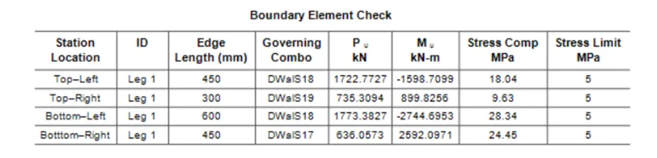
BOUNDARY WIDTH DATA:
DETAILED CALCULATIONS FOR THE SHEAR WALLS:
The detailed procedure of detailing the reinforcement bars in the shear wall is explained below brief detailing:
SECTION CLASSIFICATION:
The very first step that we need to check is the geometrical properties of the wall like the thickness of the wall, the length-to-thickness ratio, the type of shear wall, the diameter of the rebar etc. Are these properties within the limit or not according to the IS code 13920:2016? So let's check these properties one by one.
1.Thickness of the Wall:
The first property that we are going to check is the Thickness of the wall.
According to the IS 13920:2016 clause no 10.1.2, this clause states that the minimum allowable thickness of the shear wall should not be less than 150mm.
But in our case, the thickness of the shear wall given is 300mm which is greater than the 150mm suggested by the IS code 13920:2016. Hence our design is safe.
2. Length to Thickness Ratio:
The second thing that we need to check is the length-to-thickness ratio.
According to the IS 13920:2016, clause 10.1.3, the length-to-thickness ratio must be or equal to 4.
The Length of our shear wall is 1500mm.
The thickness of our shear wall is 300mm.
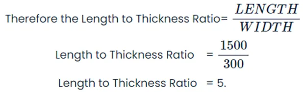
Therefore 5>4 Hence OK.
3. Shear wall type:
According to the IS 13920:2016, clause 10.1.4, suggest that we have three different types of shear walls based on their geometrical properties and these walls are listed below:
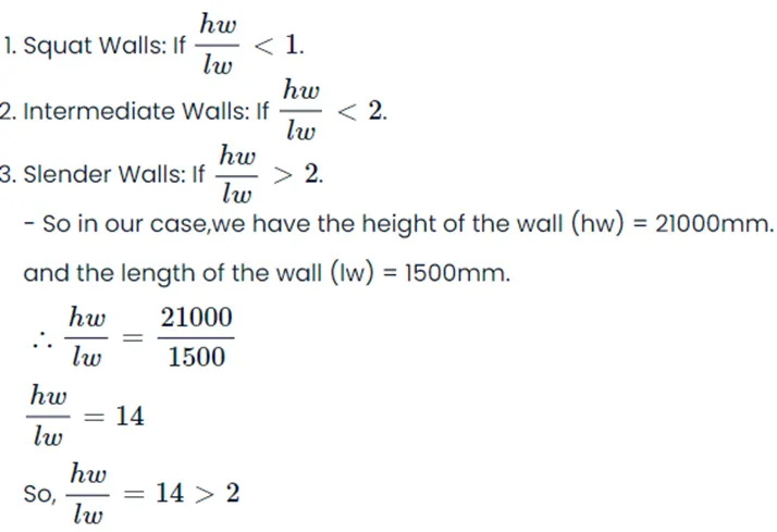
The fraction here is greater than the 2 hence OK.
Reinforcement Layer:
According to the IS 13920:2016, clause 10.1.7, the reinforcement shall be provided along with both faces of the wall thickness must be greater than 200mm.
So in this case we have a shear wall thickness of 300mm which is greater than 200mm, so we have to provide the rebars along with both faces of the wall.
4. Diameter of the Rebar:
According to the IS 13920:2016, clause 10.1.8, states that the largest diameter of the longitudinal bar shall not exceed 1/10 th of its thickness.
So in our case the thickness of our wall =300mm.
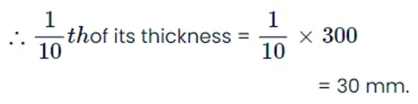
This means, we can not use any bar that exceeds the 30mm diameter value. So we will be using the 25mm diameter bar in our case because we can not use more than the 30mm diameter.
DETAILED CALCULATION:
The steps for the detailed calculations of the reinforcement bars for the shear walls from the ETABS software are discussed below.
First of all we have to divide the sections to design the walls.
We know that we can not design the walls for the entire five-storey building so we have to divide the walls along its height based on its reinforcement demand.
I have grouped the walls into two sections i.e. Section 1 and Section 2.
Section 1 = From the base up to the First Floor.
Section 2 = From the Second floor up to the Terrace level.
And according to the ETABS software we have the Boundary Width Requirement i.e., 600 mm.
So we will be designing the entire length for Section 1 as the boundary element length i.e. 600 mm.
We have a web width of 300mm but this width is much less that's why here we will be using the boundary width.
Hence for Section 1 i.e. from the base up to the first floor we will be using a boundary width of 600mm.
But as for the upper floors, the boundary element demand reduces up to 300mm.
Therefore in Section 2 i.e. from the second floor upo the terrace level we will be using the boundary element length of 300mm.
(A) CALCULATIONS FROM BASE UPTO THE FIRST FLOOR i.e Section 1:
1. Shear Demand:
As already obtained the shear demand of 750 sq. mm per 1000 mm height.
Provide 8mm diameter shear links.
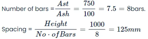
Therefore provide 8 mm diameter shear links @125mm c/c as the shear reinforcement of the entire wall.
The vertical spacing for the shear links can be obtained from clause 10.4.4 of IS 13920:2016, so according to this clause, the vertical spacing for the shear links should be 100mm.
2. Longitudinal Rebar Demand:
Here entire length is to be designed as the boundary element.
Requirement Longitudinal Reinforcement Ratio = 0.0292.
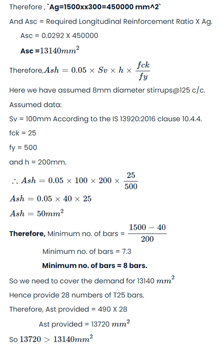
Hence OK.
Also, the spacing = 120<200mm is required.
Hence OK.
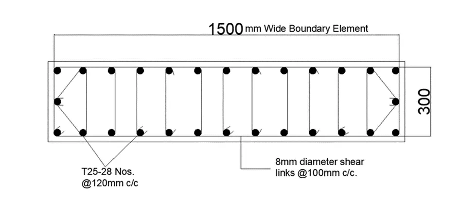
Hence provide 13 bars on one face and 13 bars on the other face making 26 bars on both sides.
Provide 2 bars along the shorter span reducing the clear spacing to 150mm. Hence OK.
Reinforcement detailing from the Base up to the First floor:
(B) CALCULATIONS FROM SECOND FLOOR UPTO THE TERRACE LEVEL i.e Section 2:
1. Design of the Web Steel:
Web Width = 900 mm.
Boundary element width = 300 mm.
Minimum reinforcement ratio for the web as per the IS 13920:2016 = 0.0025.
So here we are using the minimum reinforcement ratio for the web is 0.0030 for the safer calculations.
Therefore Ag = Web width X Boundary element width.
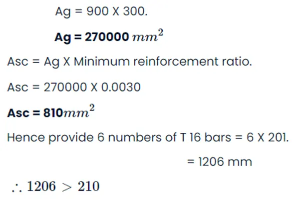
Hence OK.
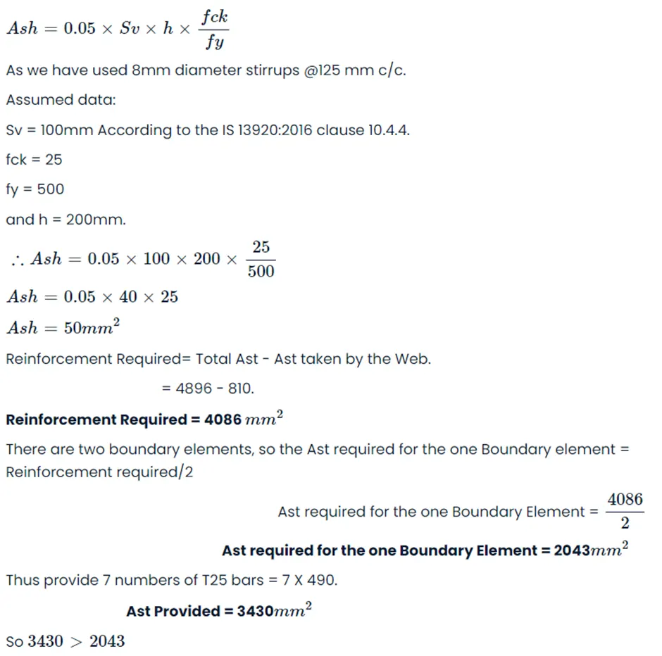
2. Design of Boundary Element:
Minimum reinforcement ratio according to the IS code = 0.008
Boundary width = 300
Hence OK.
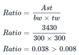
3. Reinforcement Ratio Check:
Hence OK.
Reinforcement detailing from the Second floor up to the Terrace level:
Here all the dimensions are in mm.
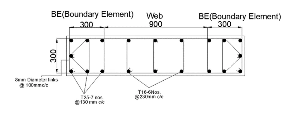
Elevation Drawing: