Analysis & Design of RCC shear walls in the model using ETABS
AIM: From etabs file of G+6 building run the analyses and for shear wall of size 300x1500 at grid A-11 in the structural model following need to be obtained:
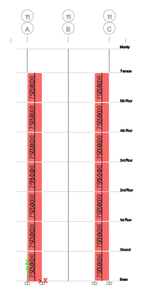
- Extract values of longitudinal steel ratio, boundary element length and shear reinforcing ratio from the design results.
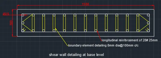
- Provide cross sectional steel arrangement of the shear wall from its base up to terrace, in compliance with provisions of IS 13920 – 2016.
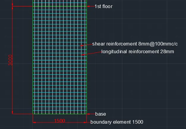
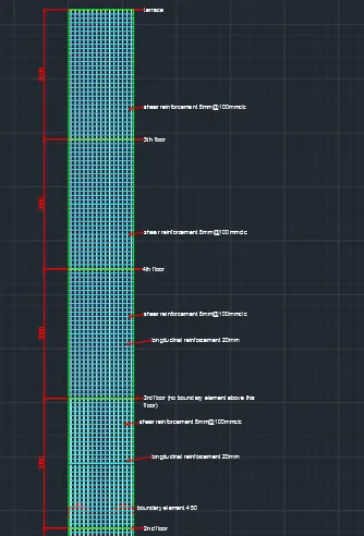
- Provide elevation drawings of the reinforcement details of the shear wall from base up to terrace using AutoCAD.
INTRODUCTION:
- Shear wall is a vertical element of a system that is designed to resist in-plane lateral forces, typically wind and seismic loads.
- The assumption are applicable only if shear wall act as vertical cantilever under seismic loads.
- According to IS-13920,shear walls are classified into 3 types-Squate shear wall(H/L<1), Intermediate shear wall(1<H/L<2),slender shear wall(H/L>2).
- Location of shear wall places a critical role,it's best to be placed at periphery of the building when the storey is open.
PROCEDURE:
- Open the etabs file and display only shear wall for better visibility of result.
- Run the analysis.
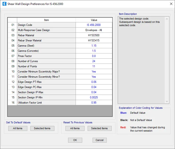
- Shear wall design>view rewise,check the codes and reinforcement details.
- Set the elevation view to grid 11.
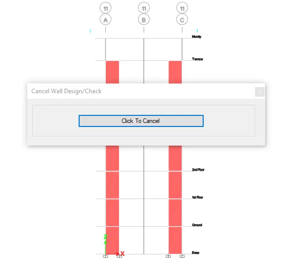
- Shear wall design>design wall.
- Shear wall design>design display info,check for P-M failure,shear failure.
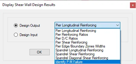
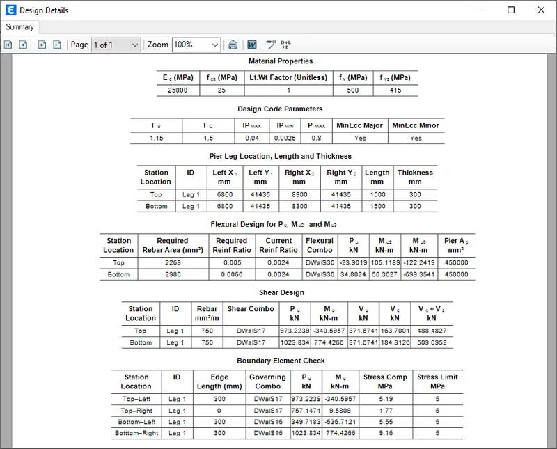
- their is no failure in the structure element as the logitudinal reinforceement ratio is <4%.
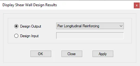
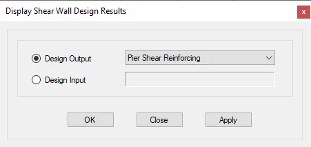
- Shear wall design>design display info>peir longitudinal steel ratio.
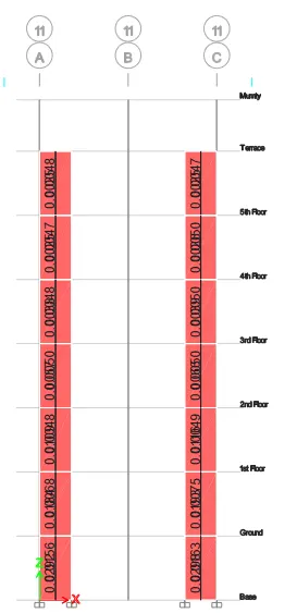
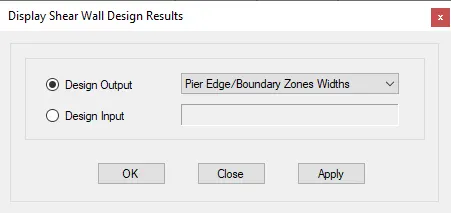
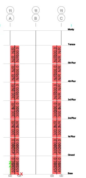
- Repeat the same for boundry element length and shear steel ratio.
CALCULATION:
BASE-
shear wall detials-
- Lw=1500,Hw=2100 and tw=300
- Hw/Lw=2100/1500=14>2,hence slender shear wall.
- Clause 10.1.8,the largest diameter of logitudinal steel bar shall not exceed 1/10th thickness of the wall-1/10*300=30mm.
- hence lets provide 25mm dia bar.
- for spacing as per clause 10.1.9,least of three(1/5th*Lw/3*tw/450mm)=1/5*1500=300mm.
longituidnal reinforcement details-
from etbas,maximum longitudinal reinforcement area,Ast= 13128 mm^2.
mimimum reinforcement ratio= 13128/300*1500= 0.029>0.008,hence ok.
from clause 10.4.4,Ash=0.05*Sv*h*fck/fy
here,sv=100mm and Ash(8mm dia)=50.24 mm^2.
50.24=0.05*100*h*25/500,h=201mm
number of bars= 13128/3.14*25*25/4= 28 bars,(13740mm^2>13128mm^2).
shear reinforcement detail-
from etabs,shear reinforcement area=750 mm^2.
lets provide 2L 8mm dia @100mm c/c(1000 mm^2> 750 mm^2),hence ok.
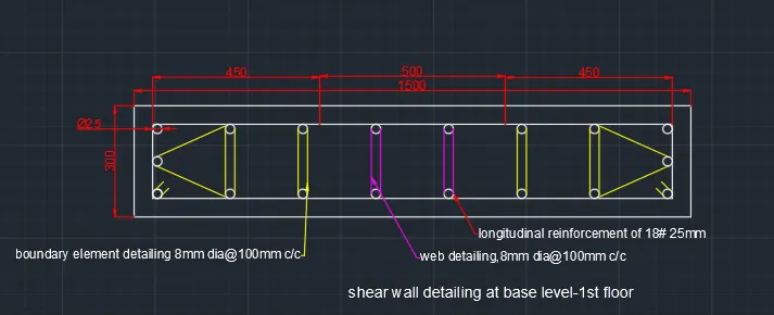
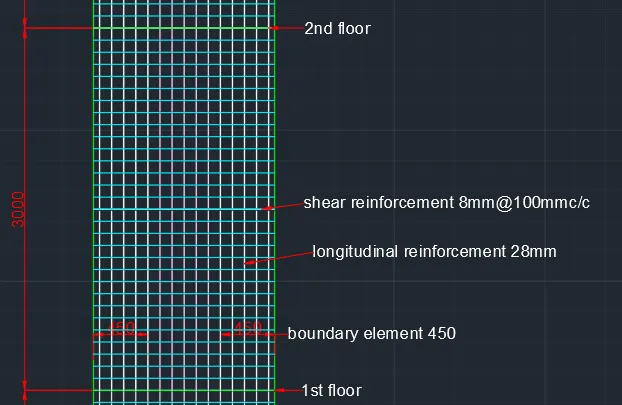
base-1st floor,(boundry element length=450mm)
longitudinal reinforcement details-
from etbas,maximum longitudinal reinforcement area,Ast= 8273mm^2.
mimimum reinforcement ratio= 8273/300*1500= 0.018>0.008,hence ok.
from clause 10.4.4,Ash=0.05*Sv*h*fck/fy
here,sv=100mm and Ash(8mm dia)=50.24 mm^2.
50.24=0.05*100*h*25/500,h=201mm
number of bars= 8273/3.14*25*25/4= 18 bars,(8340mm^2>8273mm^2).
shear reinforcement detail-
from etabs,shear reinforcement area=750 mm^2.
lets provide boundery element- 2L 8mm dia @100mm c/c(1000 mm^2> 750 mm^2),hence ok
web-2L 8mm dia @100mm c/c(1000mm^2>750mm^2),hence ok.
1st floor- 2nd floor,(boundry element length=450mm)
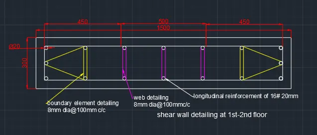
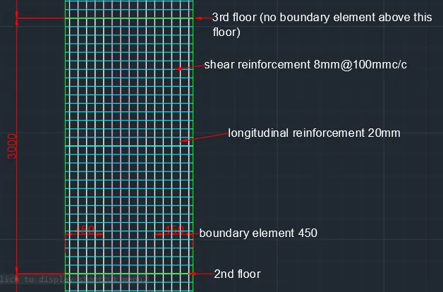
longitudinal reinforcement details-
from etbas,maximum longitudinal reinforcement area,Ast= 4896mm^2.
mimimum reinforcement ratio= 4896/300*1500= 0.01>0.008,hence ok.
number of bars= 4896/3.14*20*20/4= 16 bars,(4906mm^2>4896mm^2).
shear reinforcement detail-
from etabs,shear reinforcement area=750 mm^2.
lets provide boundery element- 2L 8mm dia @100mm c/c(1000 mm^2> 750 mm^2),hence ok
web-2L 8mm dia @100mm c/c(1000mm^2>750mm^2),hence ok.
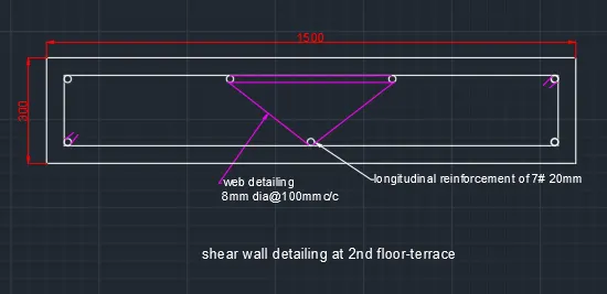
2nd floor-terrace,(boundry element not required)
longitudinal reinforcement details-
from etbas,maximum longitudinal reinforcement area,Ast= 2150mm^2.
mimimum reinforcement ratio= 2150/300*1500= 0.004>0.008,hence ok.
number of bars= 2150/3.14*20*20/4=7 bars,(4906mm^2>4896mm^2).
shear reinforcement detail-
from etabs,shear reinforcement area=750 mm^2.
lets provide - 2L 8mm dia @100mm c/c(1000 mm^2> 750 mm^2),hence ok
RESULT:
- Longitudinal steel ratio, boundary element length and shear reinforcing ratio is extracted from the design results.
- Cross sectional steel arrangment from base to terrace is calculated.
- Reinforcement details of the shear wall from base up to terrace for elevation view is drafted using AutoCAD.