Analysis & Design of RCC shear walls in the model using ETABS
aim The etabs file for a G+6 building is provided. Run the analysis and design the RCC shear walls (show in the etabs model). The following challenge deals specifically with the shear wall of size 300x1500 at grid A-11 in the structural model.
introduction
a model of the building using etabs software
the model was analyzed for sesmic loads
the shearwalls weere designed toresistant sesmic loads
the model was checked for complience with the code book
- Extract values of longitudinal steel ratio, boundary element length and shear reinforcing ratio from the design results.
- Provide cross sectional steel arrangement of the shear wall from its base up to terrace, in compliance with provisions of IS 13920 – 2016. AutoCAD application can be used for this exercise. Alternatively, it can be drawn by hand as well.
- Provide elevation drawingof the reinforcement details of the shear wall from base up to terrace.
- procedure
- open the existing etabs model
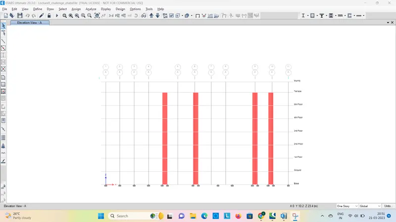
- now we have to design a particular shear wall crossing gridsa and 11 and doing on the view of terrace
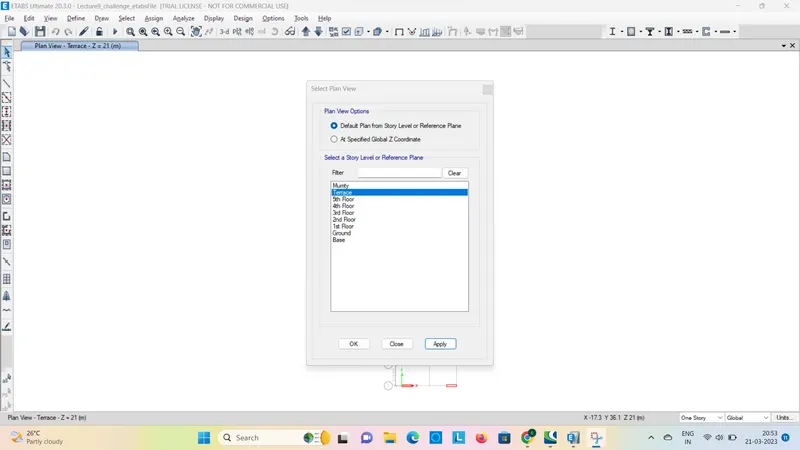
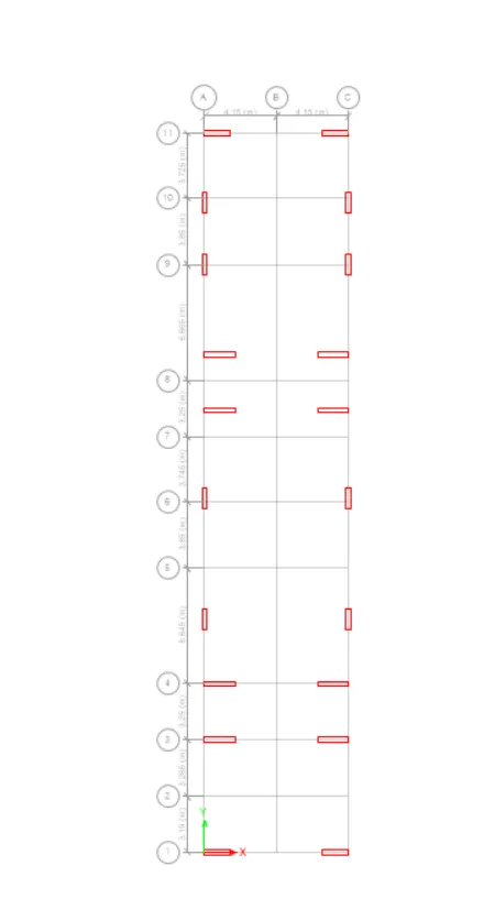
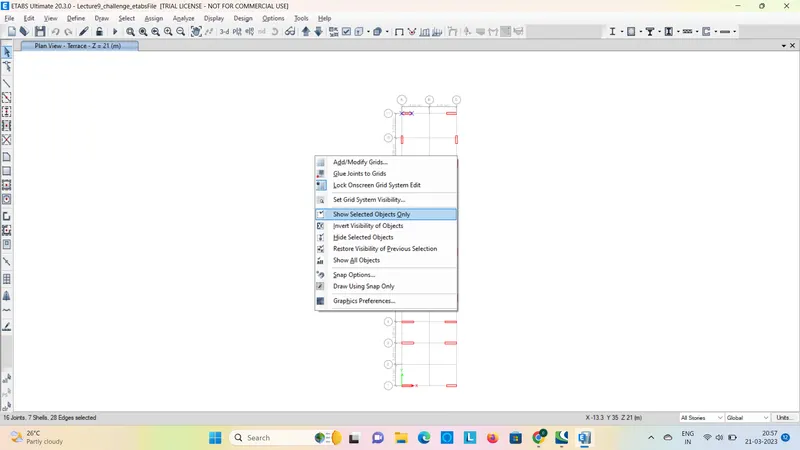
Now select the entire all stories shear wall Grid A and 11 and simply click right-click to
select the show object
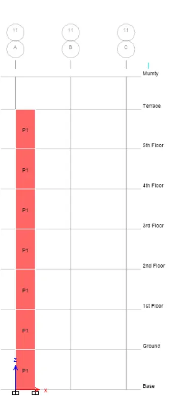
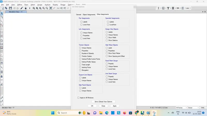
Piers are done in the above model after that to uncheck the labels
now run the analysis
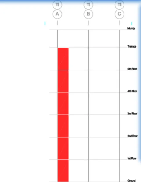
now click the shear wall design option
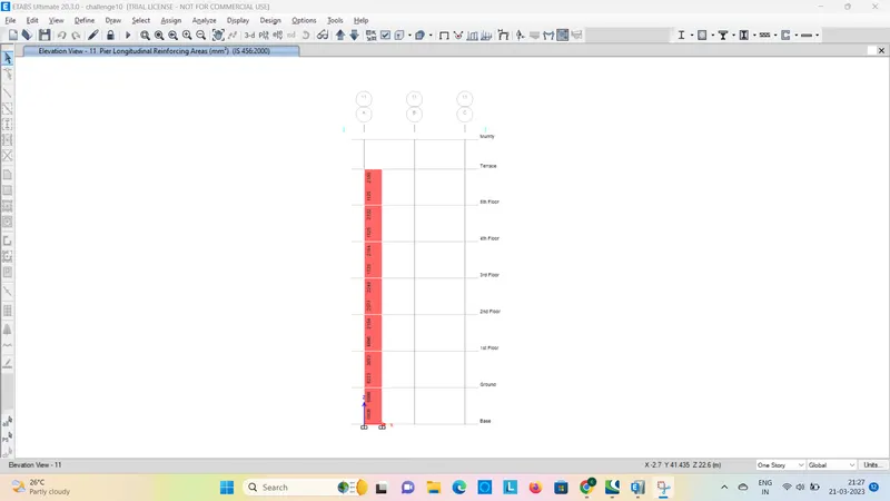
. After that dropdown the shear wall design to select the design info to change the pier
shear reinforecement boundry zone widths and horizontal reinforecement and click apply
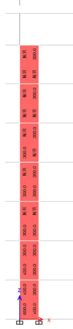
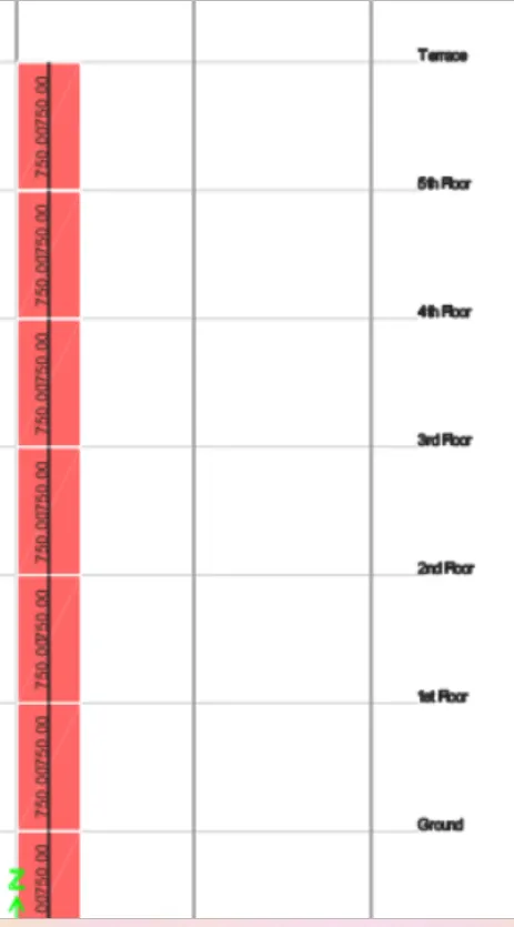
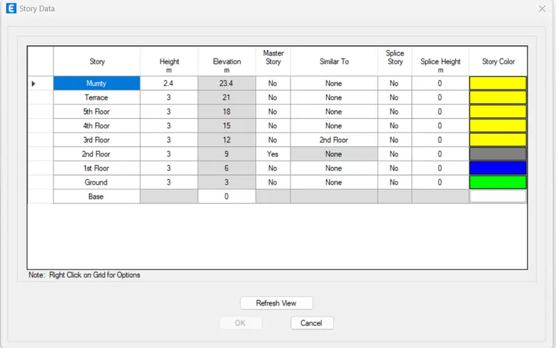
. Now note down the elevations of the model.
detailing guidlinees for shear wall
Minimum reinforcement for shrinkage & temperature
2. Ultimate limit state design rebar requirement
3. Ductility rebar requirement
Above three points whichever is greater should be drawn in RC Shear wall detailing
clasification of shear wall is 13920-2016
clause 10.14 sliender wall
hw/Lw=21000/1500=14>2
minium net vertical reinforcement as per is 13920-2016 3 23363mm2
0.0025+ 0.01375(300/1500)
minimum vertcal reinforecemnt with in boundary
1440mm2on left(600mm width in boundry)
1080 mm2 on right(4550mm width in boundry)
minimum horizontal reinforcement shear wall
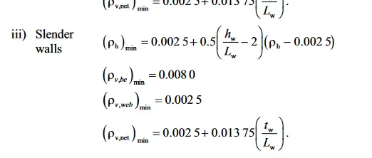
ph= 750(300x1000)=0.0025
21000
Lw=1500
(ph)min 0.0025 750mm2/m
maximum diameter of rebar for shear wall as per is 13920-2016 clause 10.1.8
1/10th of wall thickness
300/10=300mm
commercial rebar dia 250mm shall be adoptedd
confirning reinforcement spacing for boundry element as perr is 13920-2016 clause 10.4.4
1/3of minimum memeber dimension =300/3=100mm
6 times smallest main rebar=6x25=150mm
spread at max=200mm
contining reiforcement with in boundry element as per is 13920-2016 clause 10.4.4
Ash= 0.05 sv hfck/fy
Sv=150 mm h=1000mm
Ash =452mm2
shear walld etailing calculation
hw/Lw=21000/1500=14>2
minium net vertical reinforcement as per is 13920-2016 3 23363mm2

ph=0.75
minimum vertical reinforcement
minimum vertcal reinforecemnt with in boundary
1440mm2on left(600mm width in boundry)
1080 mm2 on right(4550mm width in boundry)
minimum horizontal reinforcement shear wall
0.0025+ 0.01375(300/1500)
=0.0052
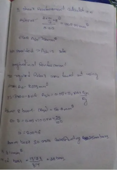
a longitudinal reinforcement calculation
the requiredd area found out usingetabs AV=13128mm2
minimum vertical reinforcement pv =131228/1500x300=0.0297>0.0080
assuming min no of barsas 8 ash=50.2mm2
50.2=005x100 Hx25/100
on solving wee get 200.96
131.28/490.87=28bars
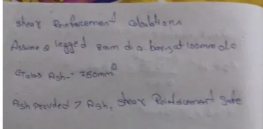
b shear reinforcement calculation
autocad drawings
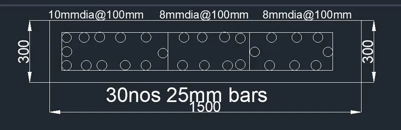
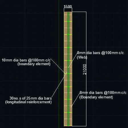
result
Analysis was performed and RCC Shear Wall was designed.
2. Extract values of longitudinal steel ratio, boundary element length, and shear reinforcing
ratio from the design results.
3. Provide cross sectional steel arrangement of the shear wall from its base up to terrace, in
compliance with provisions of IS 13920 – 2016. AutoCAD application can be used for this
exercise. Alternatively, it can be drawn by hand as well.