Analysis & Design of RCC shear walls in the model using ETABS
Aim: To extract values of longitudinal steel ratio, boundary element length and shear reinforcing ratio from the design results. To Provide cross sectional steel arrangement of the shear wall from its base up to terrace, in compliance with provisions of IS 13920 – 2016 and to provide elevation drawings of the reinforcement details of the shear wall from base up to terrace of a provided G+6 building.
Introduction: In this challenge we will mainly provide detail reinforcement design of shear wall of the given structure by achieved data from Etabs with sufficient checks to understand the safety of the deisigns.
Procedure:
Extract values of longitudinal steel ratio, boundary element length and shear reinforcing ratio from the design results of a shear wall at grid A11
- Fig A shows the plan of the given G+6 structure having located the grid A11 shear wall.
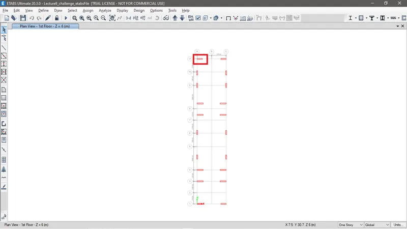
Fig A : Plan of G+6 structure in Etabs locating shearwall of grid A11.
- Now check for Piers and to do that go to Display options icon > Other assignments> check the Labels under Pier as shown in fig A1. We can see that Piers are assigned and the piers labled for Grid A11 shear wall is P1.
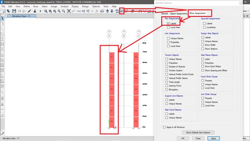
Fig A1 : Check for Piers.
- First let's run the analyse as usual so that we can achieve the further result as required. Once the analyses is done click on design shear wall icon as shown in fig B to achieve al lthe deign of the shear wall.
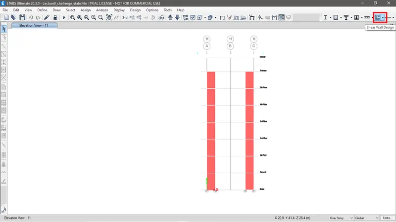
Fig B : Shear wall design
- To extract values of longitudinal steel ratio click on the dropdown box of shear wall design> Display design info. As shown in fig C.
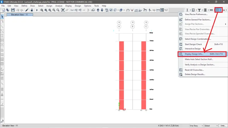
Fig C : Display design info.
- Now select Pier reinforcement ratio for data output and then click on apply and we can see the reinforcement ratio value is extracted on the shear wall of grid A11.
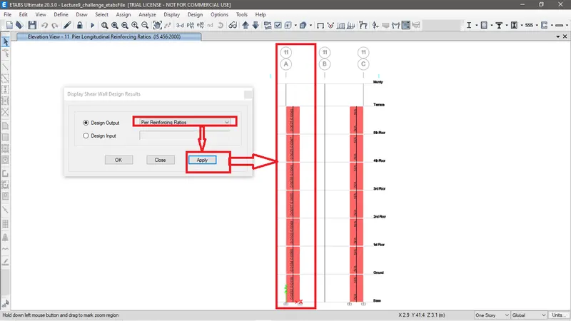
Fig D: Values of Pier reinforcement ratio
- As per the etabs design the reinforcement ratio of shear wall are as following.
For shear wall from the base - Ground floor is 2.92%
For shear wall from the Ground - 1st floor is 1.84%
For shear wall from the 1st floor-2nd floor is 1.09%
For shear wall from the 2nd floor - 3rd floor is 0.57%
For shear wall from the 4th floor - 5th floor is 0.48%
For shear wall from the 5th floor - 6th floor is 0.47%
For shear wall from the 6th floor - Terrace is 0.48%
From the above result we will have to provide the highest ratio of reinforcement throughtout the structure for better efficiency of the structure. Here we will provied 2.92% of longitudinal reinforcement which reinforcement area woulde be Ast = 300x1500x2.92%= 13140 mm2
Check for the safety of longitudinal reinforcement designed in Etabs as per IS 13920 -2016 Table 1 page no 15
As per the code the wall is identified as slender walls since the hw/Lw >2 (21/1.5= 14).
Hence the net minimum vertical reinforcement is as shown in fig D1.
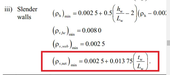
Fig D1: Slender wall min vertical reinforcment formula.
Minimum required longitudinal reinforcement is 0.0025+0.01375(300/1500)=0.00525 i.e around 0.525% that would be Astreq = 300X1500X0.525%=2362.5mm2.
Since Etab designed Ast is greater than min required Ast. Hence it is safe.
And as per the clause 10.4.2.1 the vertical reinforcement shall not be less than 0.8% and more than 6%.
Min vertical reinforcement for left boundary element is 600X300X0.8% = 1440 mm2
Min vertical reinforcement for right boundary element is 450X300X0.8% = 1080 mm2
Hence safe.
- Now to extract the length of boundary elements of the shear wall select the design output as Pier Edge/ Boundary zones widths in Display shear wall design results and click on apply as shown in fig E.
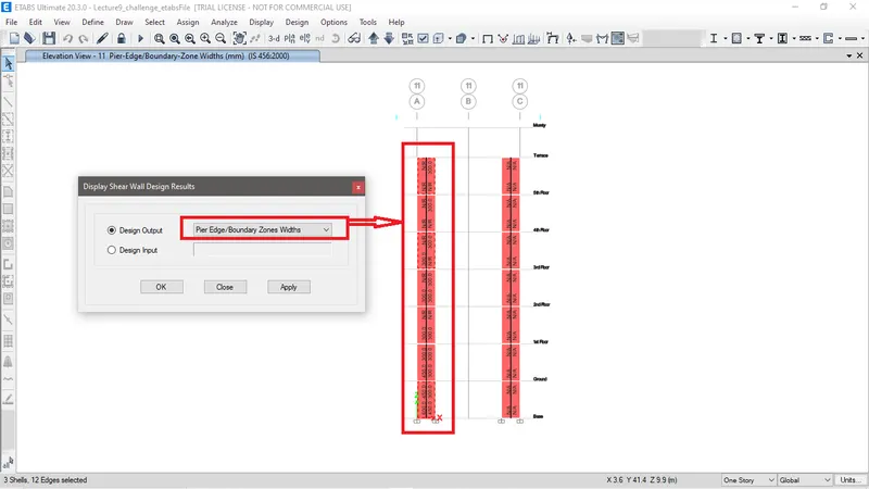
Fig E: Length of boundary elements.
- As per the etabs design the length of boundary elements of shear wall are as following.
For shear wall from the base - Ground floor is 600mm for left boundary element and 450 for right boundary elements.
For shear wall from the Ground - 1st floor, the left bounday element length is 450mm and right boundary element lengthe is 300mm.
For shear wall from the 1st floor-2nd floor , the left bounday element length is 300mm and right boundary element lengthe is 300mm.
For shear wall from the 2nd floor - 3rd floor , the left bounday element length is 300mm and right boundary element lengthe is 300mm.
For shear wall from the 4th floor - and above, the left bounday element is not required and right boundary element lengthe is 300mm.
Here the highest length is given in the base - Ground floor. Hence boundary element for left will be provided 600 mm and for the right is 450 mm.
- Now to extract the shear reinforcing of the shear wall select the design output as Pier shear reinforcing in Display shear wall design results and click on apply as shown in fig F.
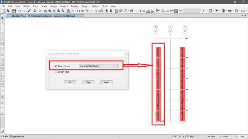
Fig F: Pier shear reinforcing.
As per Etabs design Shear reinforcement of 750 mm2 / m to be provided through out.
Check for shear reinforcing as per IS 13920 - 2016 as shown in fig G.
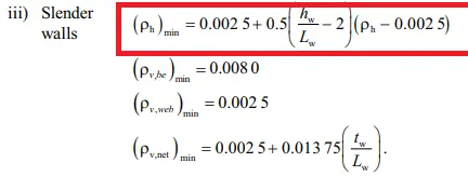
Fig G: Min horizontal reinforcement
Min horizontal reinforcement = 0.0025 + 0.5 ((21000/1500)-2) ((750/300X1000)-0.0025) = 0
Hence provided reinforcement design is as same as min shear reinforcement. Hence it is satisfied.
- Max dia of bar to be provide as per IS 13920 2016 clause 10.1.8 is shown as fig H.

Fig H: IS 13920 2016 clause 10.1.8.
Largest diameter = 300/10 = 30
We can provide maximum 25 mm dia bar as per commercial provision.
- With all the details above Fig I shows the Cross section details of the shear wall with detailed reinforcement and Fig J shows the elevation of the reinforcement of the shear wall.
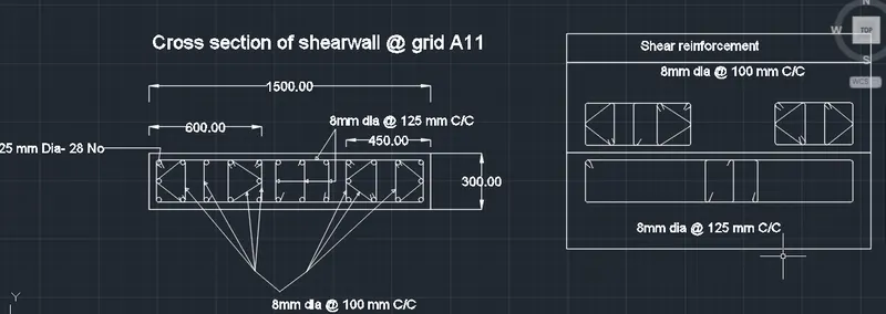
Fig I: Shear and longitudatinal reinforcement cross section details.
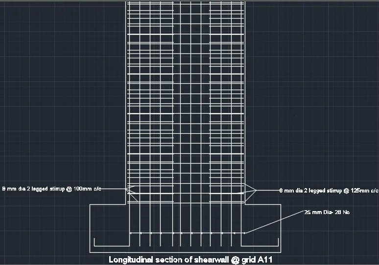
Fig I: Shear wall reinforcement elevation.
Conclusion
The shear wall is analysed by Etabs and extracted design is used to design the reinforcement of the shear wall with all the necessary checks as per IS 13920 2016 and Structural drawing is created through Autocad.