Analysis & Design of RCC shear walls in the model using ETABS
Aim: To create a G+6 building is provided and to run analysis and design the RCC shear walls as shown in the given attachment.
Introduction: To create a G+6 building is provided and to run analysis and design the RCC shear walls as shown in the given attachment.
Procedure:
- Open the drawing which is given in the attachment.
- Select the elevation view option.
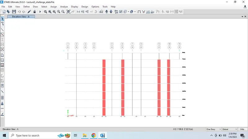
- Now click on the plan view option.
- And select floor option.
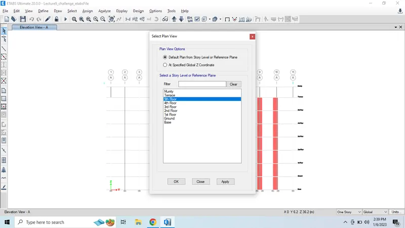
- Now we can see the floor plan and select all stories option.
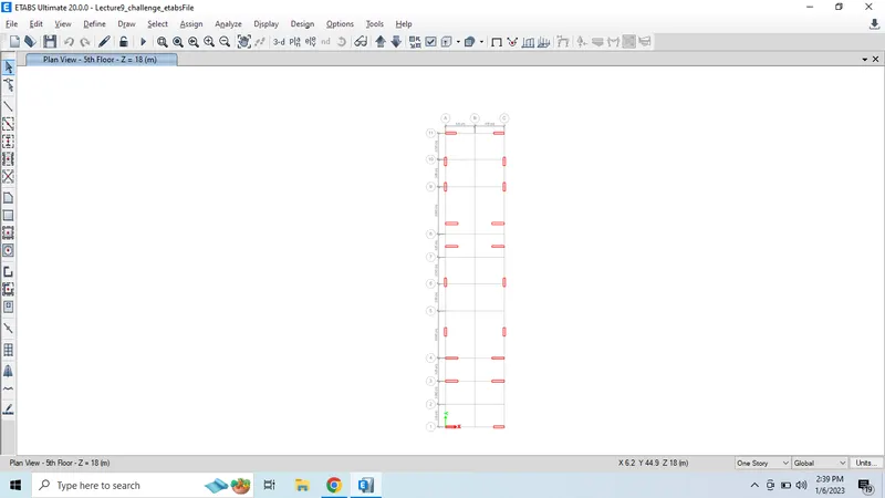
- Select the column for all the stories.
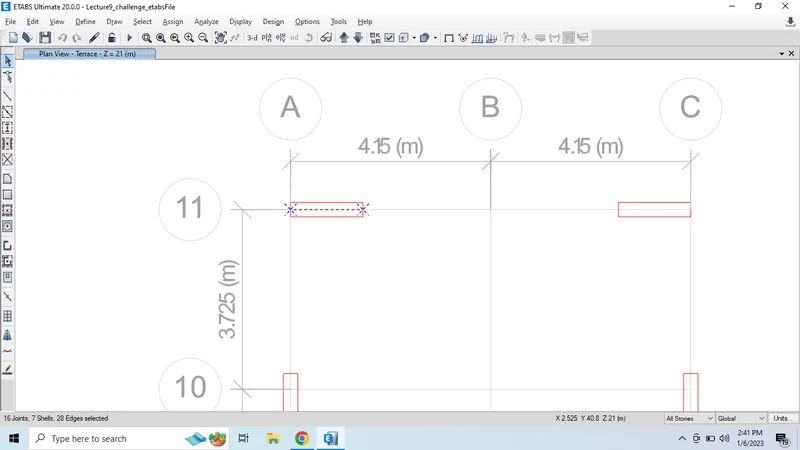
- Right click on the cursor and click on the selected objects.
- And click ok.
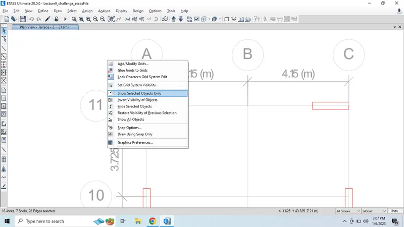
- Select show selected objected objects only.
- And click enter.
- Here we can see the selcted objects for all the floors.
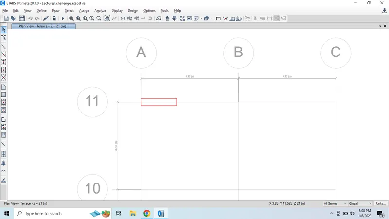
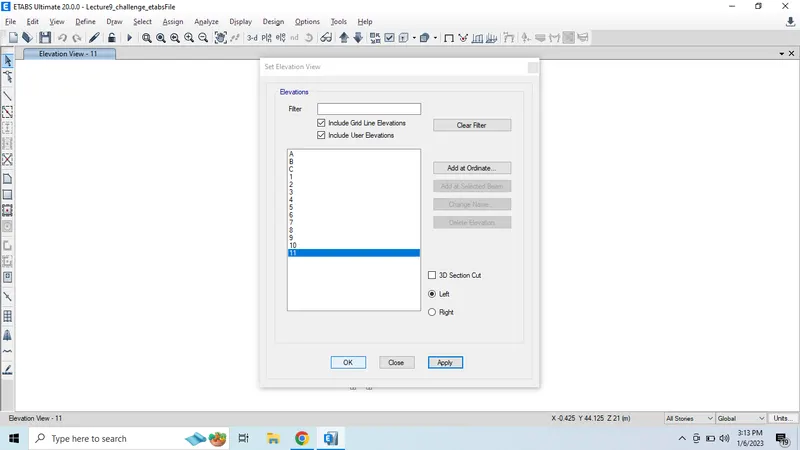
- Now select elevation view option and select one floor option.
- Then click on apply and click ok.
- Now we can see the drawing along the grid level option.
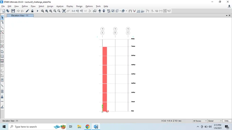
- Now click on Run analysis option.
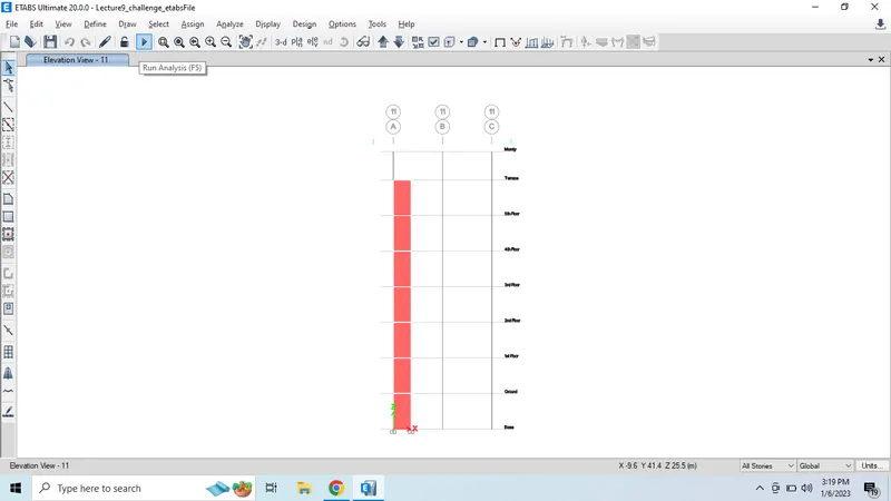
Now we can see the deflection values.
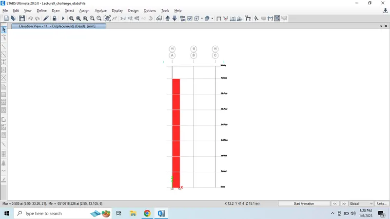
- Now we can see the elevation view of the deflection values.
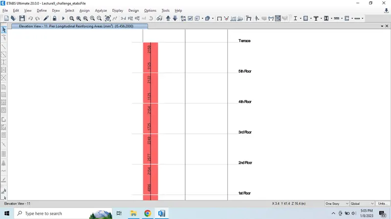
- We can see the Longitudinal reinforcing areas.
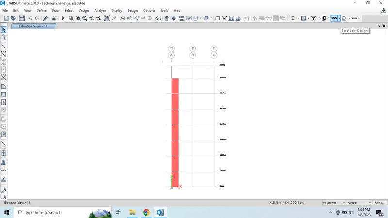
- Now click on the display design option from the steel bar.
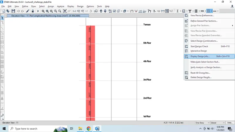
- Select pier shear reinforcement values.
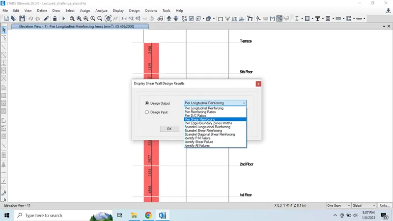
- Click on apply option and click ok.
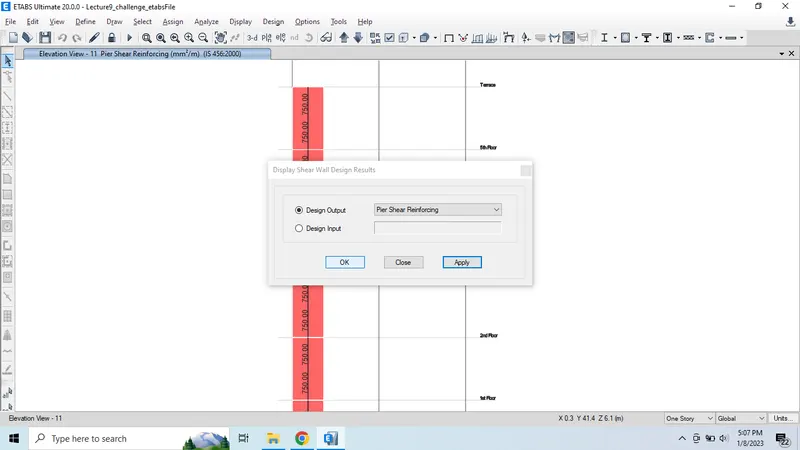
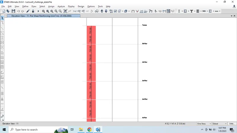
- Now we can see the Shear Reinforcement option.
- We can see the horizantal reinforcement values.
-
- Now select the boundary edge option.
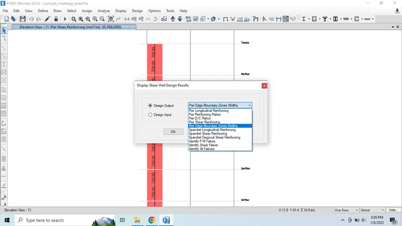
- Now select apply option and click on ok.
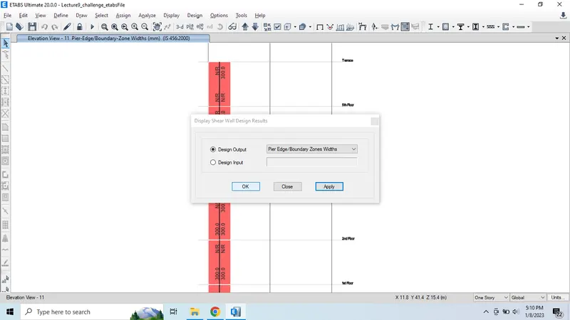
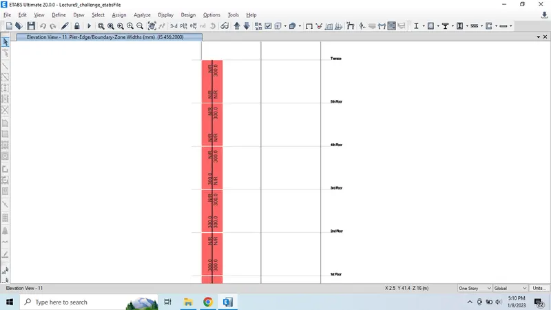
- Now we can see the boundary edges values.
- Select Edit stories and grid systems.
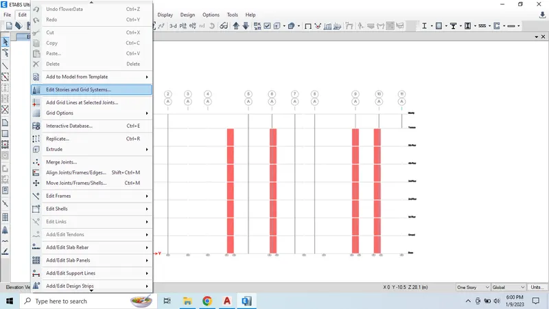
- Now click on modify option.
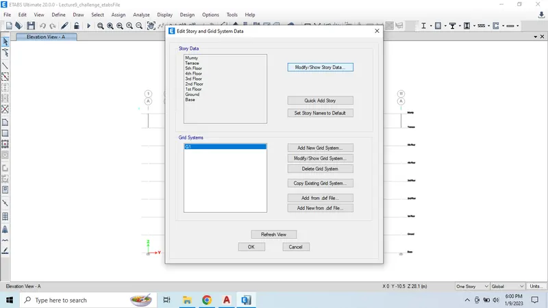
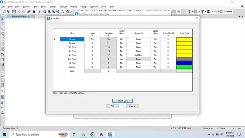
- Here we can see the story values.
Classification of shear wall as per IS-13920-2016 clause 10.14 for Slender wall
hw/Lw = 21000/1500
= 14>2
Minimum net vertical reinforcement as per IS-13920-2016 Table-1 (iii)
= 0.0025 + 0.01375 (300/1500)
= 2363 mm^2
Minimm vertical reinforcement within boundary element Table-1 (iii)
1440 mm^2 on left (600mm width boundary element)
1080 mm^2 on right (450mm width boundary element)
Minimum horizantal reinforcement in shear wall as per IS-13920-2016 Table-1 (iii)
(ρh)min = 0.0025 + 0.5(hw/Lw-2) (ρh-0.0025)
ρh = 75/(300X1000) = 0.0025,
hw = 21000, Lw = 1500
(ρh)min = 0.0025 + 0.5 (21/15-2) x 0
(ρh)min = 00025 which is the same 750 mm^2/m
Maximum diameter of rebar for shear wall as per IS-13920-2016 clause 10.1.8
1/10th of wall thickness = 300/10 = 30mm
Commercial rebar diameter 25mm shall be adapted.
Confining reinforcement spacing for boundary element as per IS-13920-2016 clause 10.4.4
(i) 1/3 of minimum member dimension = 300/3 = 100mm
(ii) 6 times smallest main rebar = 6x25 = 150mm
(iii) 150mm permissible if vertical bars are spaced at maximum 200mm
maximum spacing of confining reinforcement in boundary element 150 mm
Confining reinforcement within boundary element as per IS-13920-2016 clause 10.4.4
Ash = 0.05 Sv h Fck/fy
sv = 150mm, h = 1000mm
Ash = 452mm^2
- Overall stirrup 1 link 8mm dia 250mm spacing
- B.E stirrup 2 links 8mm dia 150mm spacing
28 numbers 25mm dia main bar 2 numbers 12mm dia additional boundary element bar.
2 Numbers 12mm dia addition boundary element bar.