Analysis & Design of RCC shear walls in the model using ETABS
AIM
- To run the analysis and design the RCC shear wall
- To extract values of the longitudinal steel ratio,boundary element length and shear reinforcement ratio from design results
- To provide the elevation drawings of the reinforcement details of shear wall
INTRODUCTION
ETAB or ETABS they mean the same. Its full form is extended three-dimentional analysis of building system. It is an engineering software product that caters to multi-story building analysis and design. ETABS offers a single user interface to perfom modelling, analysis, design and reporting.There is no limit to the number of modelling windows,model manipulation views and data views.
OBJECTIVES
- To know the design of RC shear wall using ETABS analysis
- To know the basics of RC shear wall reinforcement detailing with respect to primary standards
- To ensure the ductility reinforcement required by IS-13920-2016 been satisfied in reinforcement drawing
PROCEDURE
STEP:1
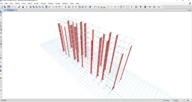
- Open the attached file in ETABS
STEP:2
- After opening the file,we should be able to see all the shear wall provided at all the floors from the top plan view
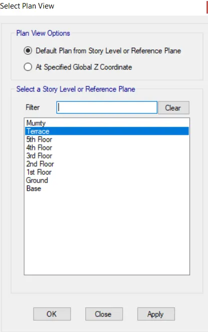
- Select the terrace plan view and click apply
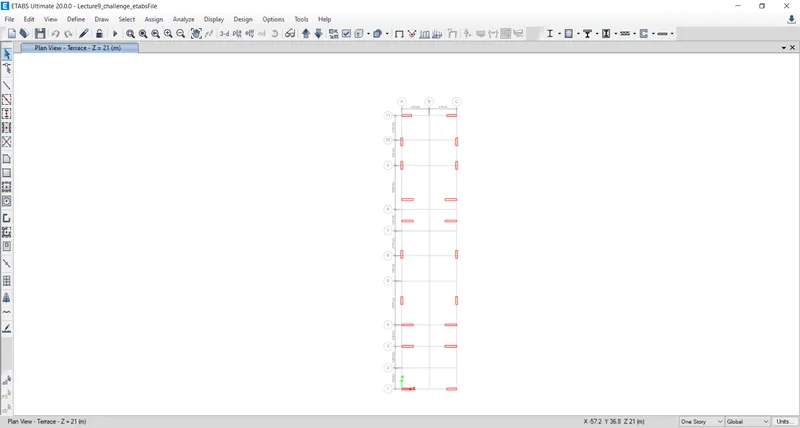
- Select the all stories option present at the right bottom corner
- Then select the grid A-11
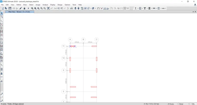
- After selecting the grid A-11 shear wall at all the floors,right click at the workspace and select the show selected objects only
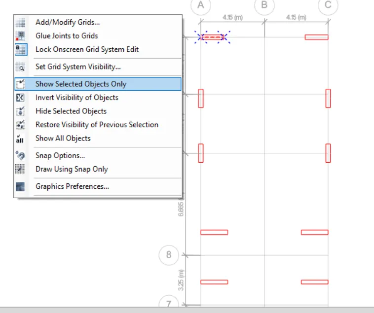
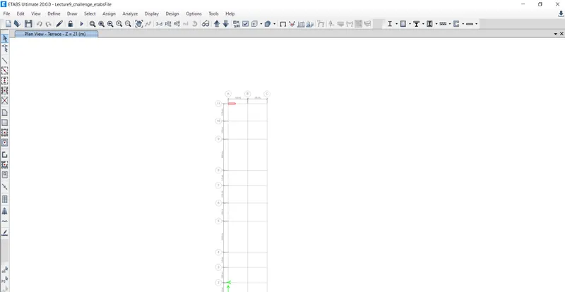
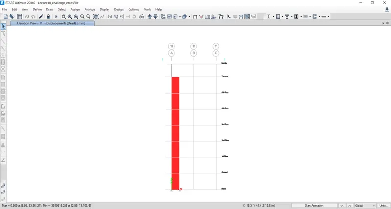
- To see the elevation view of the showing shear wall at grid A-11
- Select the elevation view tool
- Tab will be opened and from that select the elevation11
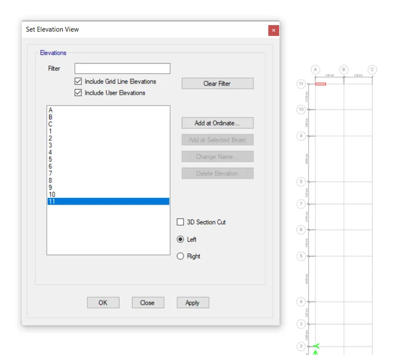
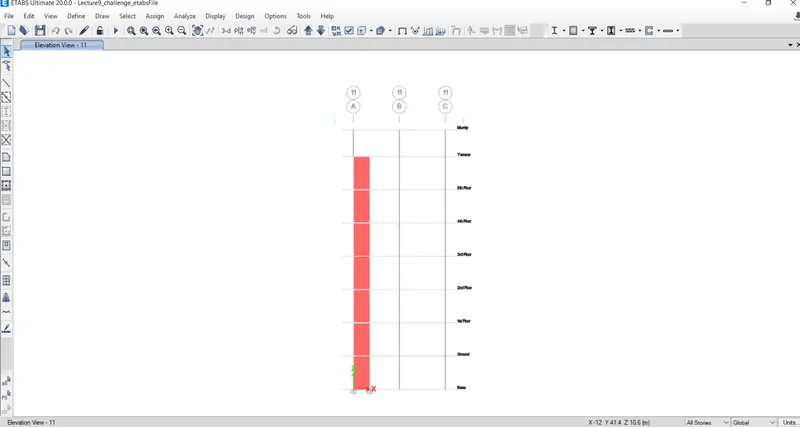
- Make sure that the pier label is applied at all the shear walls before
- After that the shear wall can be analyzed and it should be done by clicking Run Analysis
STEP:3
Shear Wall Design
- We have to click on the shear wall design icon
- Now we have to wait till the design completes
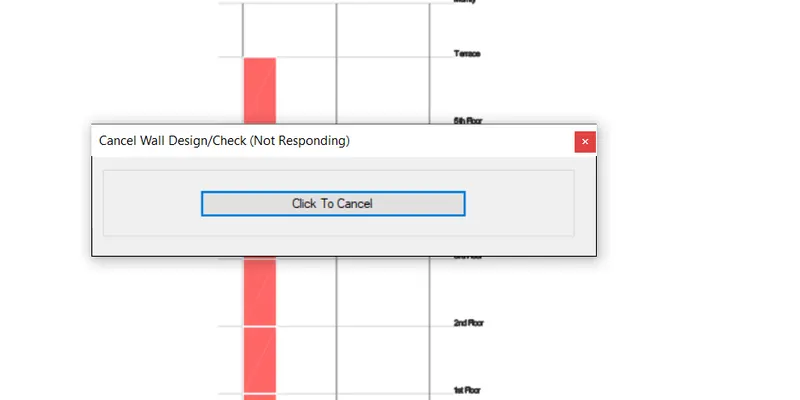
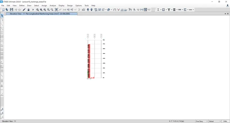
- After the completion of shear wall design,to know the other reinforcement member requirements for the shear wall
- we need to select the DISPLAY DESIGN INFORMATION
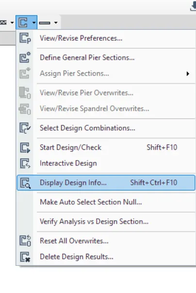
- After selecting the 'display design info' option the new tab appears, in that we select pier longitudinal reinforcement and click the ok button
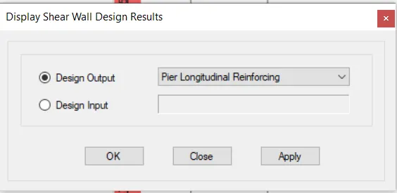
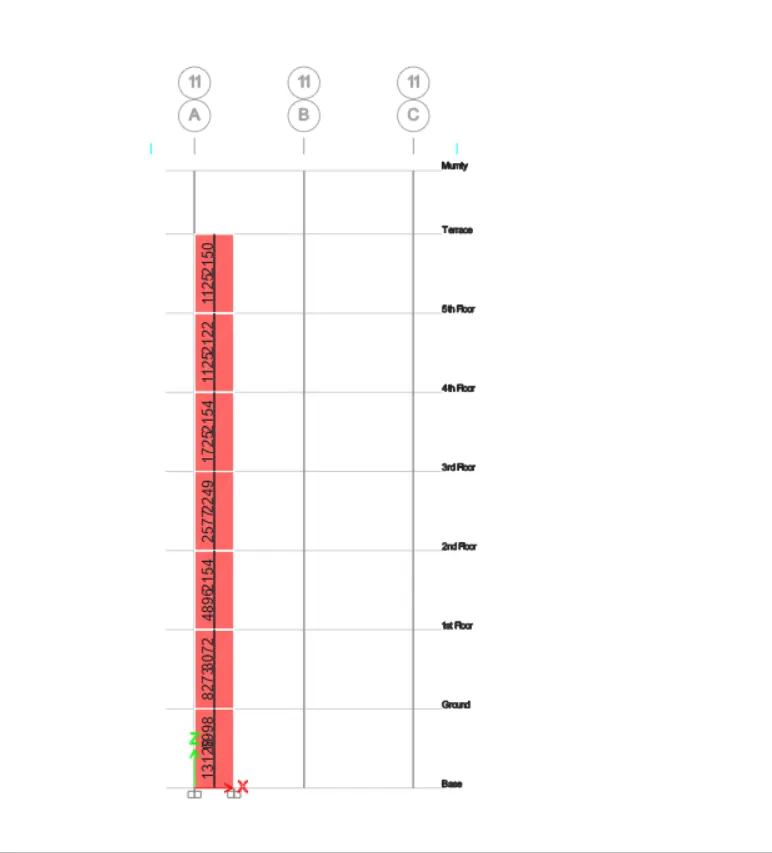
- pier Longitudinal reinforcement details will appear
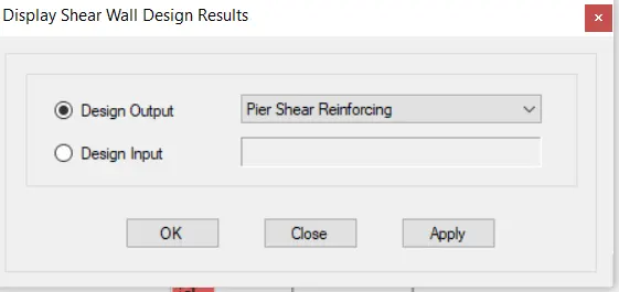
- Then again select 'display design info' option the new tab appears, in that we select pier shear reinforcement ,click the ok button
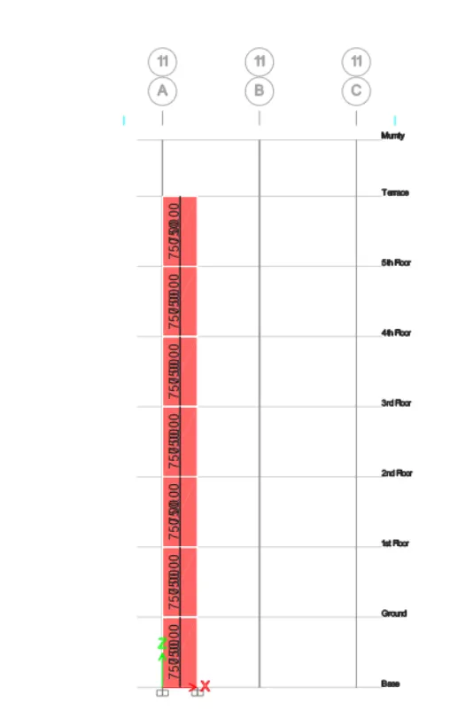
- Pier shear reinforcement details will appear
- Then again select 'display design info' option the new tab appears, in that we select pier edge/boundary zones width ,click the ok button
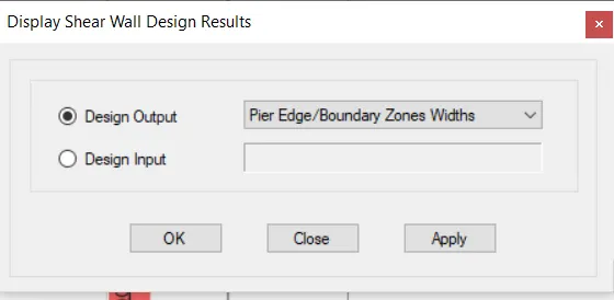
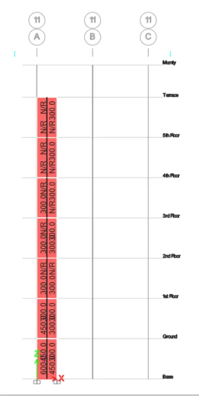
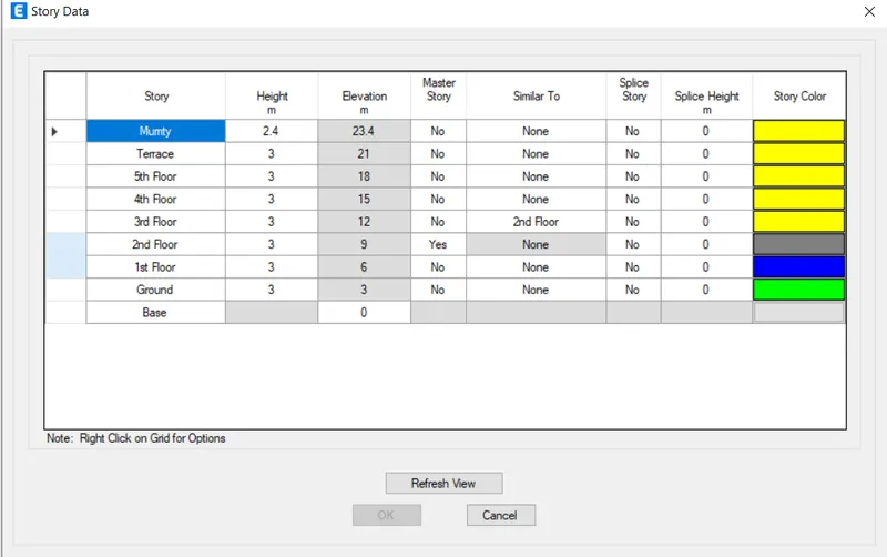
- Check the stories and grids
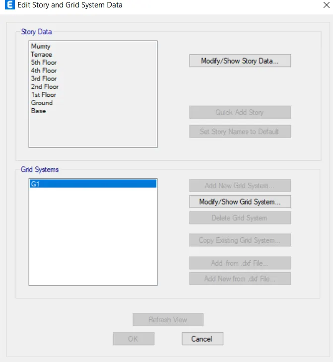
- For that go to Edit story and grid system tab
- From that select modify/show story data
STEP:4
DETAILING GUIDELINES FOR SHEAR WALL:
- Minimum reinforcement of shrinkage and temperature
- ultimate limit state design rebar requirements-----whichever is greater ,should be drawn in RC shear wall detailing
- Ductility rebar requirement
a.Detailing guidelines for shear wall:
classification of shear wall as per IS 13920-2016 clause 10.1.4
hw/Lw = 21000/1500 = 14
hence ,14 is greater thsn 2,so the shearwall design may be of slender wall type
b.Minimum net vertical reinforcement as per IS 13920-2016 table1(3)
taking area from top view
=0.0025+0.01375(300/1500) = 2363mm^2
c.Minimum vertical reinforcement within the boundary element table 1(3)
1440mm^2 on left (600mm with boundary element)
1080mm^2 on right (450mm with boundary element)
d.Minimum horizontal reinforcement in shear wall as per IS 13920-2016 table1(3)
we have formula for value of p is unknomn,
p = 750/(300/1000)=0.0025
we having, hw=21000,Lw=1500
so,
(ph)min = 0.0025+0.5(21/15-2)*0
(ph)min=0.0025(same as 750mm)
e.Minimum diameter of rebar for shear wall as per IS 13920-2016 clause 10.1.8
1/10th of wall thickness = 300/10=30mm
hence, available rebars diameter are 25,32mm
so,using 25mm dia rebar
f.Confining reinforcement spacing for boundary element as per IS 13920-2016 clause 10.4.4;
As per the conditions,maximum spacing of confining reinforcement in boundary element will be 150mm
g.Confining reinforcement within boundary element as per IS 13920-2016 clause 10.4.4:
Ash = 0.05 sv h fck/fy
where,
sv= 150mm
h=1000mm
substituting the value
Ash= 452mm^2
DRAWINGS:
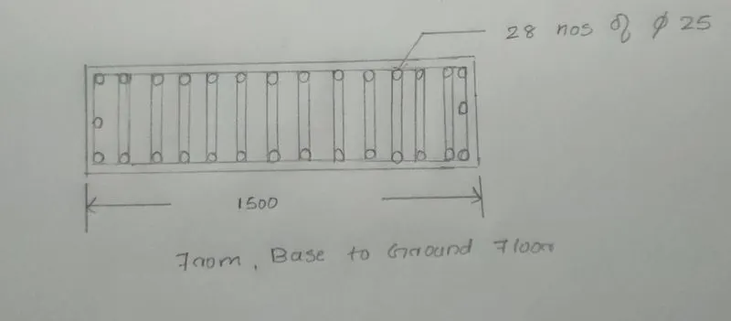
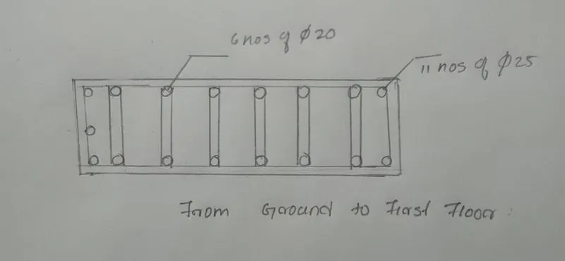
RESULT
- We have run the analysis and designed the RCC shear walls ( show in the etabs model) for size 300*1500 ar grid A-11 in the structural model
- Also we extracted the values of longitudinal steel ratio, boundary element length and shear reinforcing ratio from the design results
- Also provided cross sectional steel arrangment of the shear wall from its base up to terrace , in compilance with provisions of IS 13920-2016