Analysis & Design of RCC shear walls in the model using ETABS
The ETABS file for a G+6 building is provided. Run the RCC shear walls' analysis and design (shown in the ETABS model). The following challenge deals specifically with the shear wall of size 300x1500 at grid A-11 in the structural model.
· Extract values of longitudinal steel ratio, boundary element length and shear reinforcing ratio from the design results.
· Provide cross-sectional steel arrangement of the shear wall from its base up to the terrace, in compliance with IS 13920 – 2016. AutoCAD application can be used for this exercise. Alternatively, it can be drawn by hand as well.
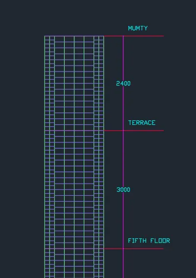
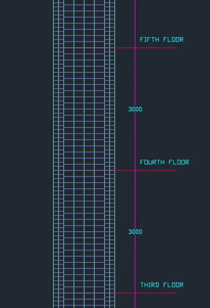
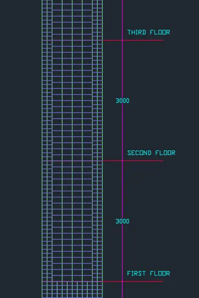
· Provide elevation drawings of the reinforcement details of the shear wall from the base up to the terrace.
AIM
- To run the analysis and design the RCC Shear walls for the given ETABS model.
- To extract the values of longitudinal steel ratio, boundary element length, and shear reinforcing ratio from the design results.
- To provide the cross-sectional steel arrangement of the shear wall from its base up to the terrace, in compliance with provisions of IS 13920-2016
- To provide elevation drawings of reinforcement details of the shear wall from base to terrace.
INTRODUCTION
A shear wall is a structural member used to resist lateral, typically wind and seismic loads. It resists the loads due to Cantilever Action. In other words, Shear walls are vertical elements of the horizontal force resisting system. Lateral forces caused by wind, earthquake, and uneven settlement loads, in addition to the weight of structure and occupants, create powerful twisting (torsional) forces. These forces can tear (shear) a building apart. Reinforcing a frame by attaching or placing a rigid wall inside it maintains the shape of the frame and prevents rotation at the joints. Shear walls are especially important in high-rise buildings subject to lateral wind and seismic forces. They also provide adequate strength and stiffness to control lateral displacements.
A shear wall consists of a web and boundary elements on either side. These boundary elements in shear walls are subjected to alternate compression and tension when it is subjected to lateral forces, hence it is necessary to provide special confinement reinforcement for the boundary elements.
IS13920-2016 provides guidelines on several aspects of shear wall detailing.
- The thickness of the wall (clause 10.1.2)
- Minimum ratio of wall length to thickness (clause 10.1.3)
- The largest diameter of longitudinal steel bar (clause 10.1.8)
- Maximum spacing of horizontal and vertical reinforcement (clause 10.1.9)
- Conditions for the base of the shear wall (clause 10.1.10)
- Minimum reinforcement in RC shear wall (clause 10.1.6)
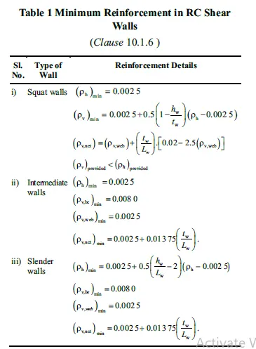
- From clause 10.1.4, walls can be categorized as squat walls, intermediate walls, and slender walls as given below:
- Squat wall, if hw/Lw < 1
- Intermediate wall, 1 ≤ hw/Lw ≤ 2
- Slender wall, hw/Lw > 2
- Minimum shear reinforcement in the boundary element of the RC shear wall can be determined from the formula:
`A_(sh)=0.05* S_v* h* f_(ck) /f_y`
PROCEDURE
Open the given ETABS model.
Go to the analysis tab and check the model and Run Analysis.
Go to Display> Show Tables> Analysis Result> Structure Output> Base Reactions
Display the reactions due to seismic forces
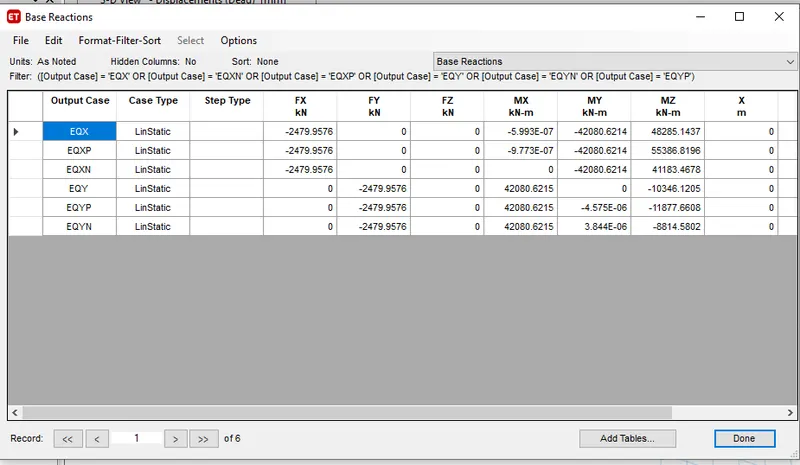
Change the view to Plan> Base
Go to Display> Support Reaction
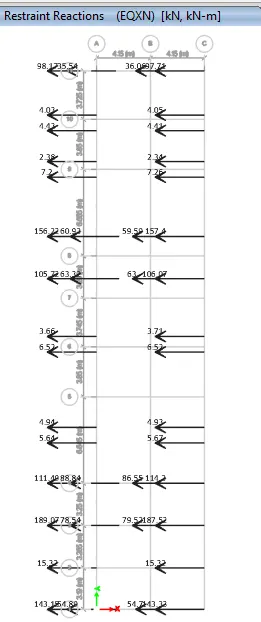
When we divide the base shear taken up by the shear wall divided by the total base shear of the building will get the percentage of the shear force taken up by the shear wall and if that is more than 80%, that means no more shear wall is required to resist shear.
Change the view to Elevation> 11
Display pier labels
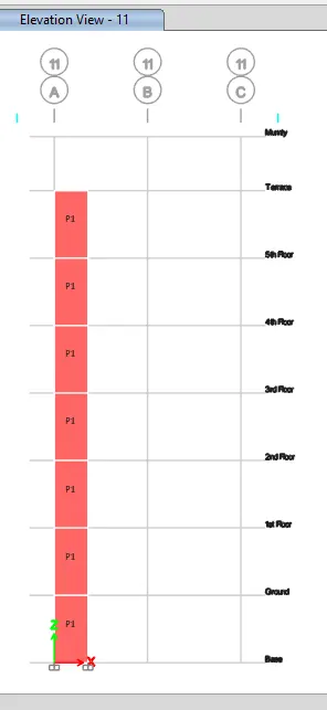
Go to shear wall design> View/Revise preferences
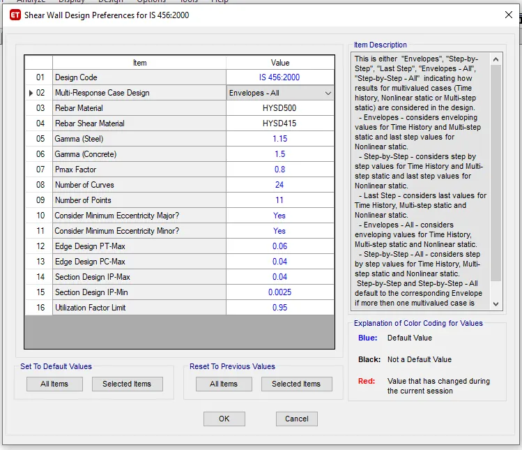
Start Design/Check
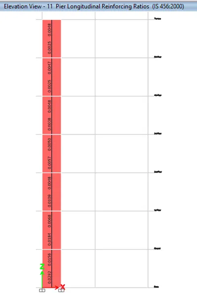
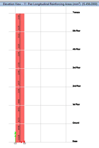
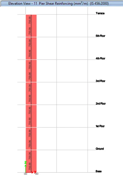
Now extracting the design results as shown below
Pier Reinforcing Ratio
Pier Longitudinal Reinforcing Area
Pier Shear Reinforcing Area
Boundary Element Width
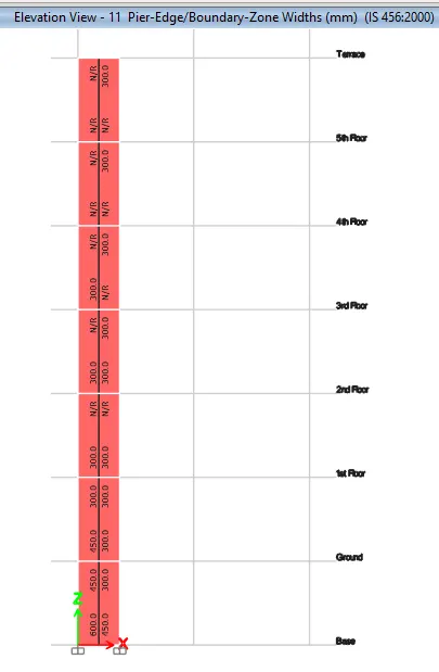
DESIGN SUMMARY
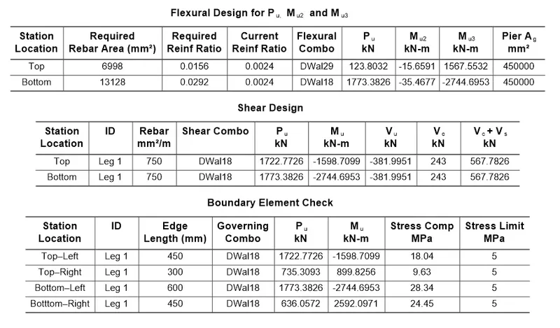
Design Calculations in accordance with the IS-13920:2016
- The thickness of the wall
As per clause 10.1.2, the minimum allowable shear wall thickness is 150mm; in our case, we have a 300mm thick shear wall. Hence OK.
- Minimum ratio of wall length to thickness
As per clause 10.1.3, the minimum allowable length to thickness ratio must be greater than or equal to 4.
We have 1500mm as the length and 300mm thickness.
Therefore,
1500/300 = 5 > 4 Hence OK.
- Reinforcement layers
As per clause 10.1.7, reinforcement shall be provided along with both faces of the wall if the wall thickness exceeds 200mm.
As we have a 300mm thick shear wall, we have to provide the rebars along both the faces of the wall.
- Largest diameter of the rebar
As per clause 10.1.8, the largest diameter of the longitudinal bar of the shear wall shall not exceed 1/10th of its thickness.
So, 1/10 x 300 = 30mm.
Provide 25mm diameter bars
- Shear wall type
Lw=1500, hw=21000
hw/Lw= 21000/1500 = 14 >2
therefore the wall is categorised as a slender wall
- Minimum reinforcement in RC shear wall
(ρh) min= 0.0025 + 0.5 (hw /Lw -2) (ρh -0.0025)
(ρv, be) min = 0.0080
(ρv, web) min = 0.0025
(ρv, net) min = 0.0025 + 0.01375 (tw/Lw)
The entire shear wall cannot be detailed in one go. We have to divide the wall along its height based on the reinforcement demand on each floor. So, following the ETABS output, we have grouped the wall into two sections. The first section runs from the base until the first floor and the second one follows up to the terrace level.
DETAILING FROM THE BASE TO THE FIRST FLOOR
Shear Reinforcement
ρh = 750/1000x300 =0.0025
(ρh) min= 0.0025 + 0.5 (21000/1500 - 2) (0.0025 - 0.0025)
(ρh) min= 0.0025
Ast, min = 0.0025 x 1000 x 300 = 750mm2
Provide 2 legged 10 mm diameter bar
Sv= 2*0.785*10*10*1000/750
=209.33mm
Sv should not exceed [Lw/5, 3.tw, 450mm]
[1500/5 = 300, 3*300=900, 450]
Provide Sv=150mm c/c
However, the vertical spacing for shear links within the boundary element shall be governed by clause 10.4.4 which is 100mm.
Ast, prov. = 2*0.785*10*10*1000/100 = 1570mm2 > 750mm2
Hence OK
Longitudinal Reinforcement
(ρv, net) min = 0.0025 + 0.01375 (tw/Lw)
=0.0025 + 0.01375 (300/1500)
=0.0025 + 0.01375 x 0.2
=0.00525
Ast = 0.00525 x 1500 x 300 = 2362.5mm2
As per ETABS results Ast, required = 13128mm2
(ρv,be) min = 0.0080
Reinforcement ratio (ρ) = 13128/1500 x 300 = 0.0291 > 0.008
Hence OK
Ash: Area of the cross-section of bar forming link
Ash =0.05x Sv x h x fck/fy
Sv should not exceed [tw/3, 6.d, and 100mm]
Take Sv=100mm
h: longer dimension of rectangular confining link
fck = 25MPa fy = 500MPa
Ash = 0.785*10*10 = 78.5,
h = (78.5*500)/ (0.05*100*25) = 314mm
h should not exceed [Lw/5, 3.tw, 450mm]
[1500/5 = 300, 3*300=900, 450]
Take h=150mm c/c
Also, for Ast = 13128mm2
No. of bars = 13128/0.785*25*25 = 26.75, Take 28
Ast, prov. = 28*0.785*25*25 = 13738> 13128 OK
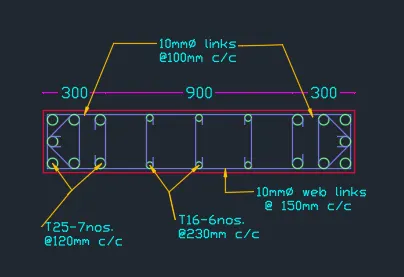
So, provide 13 bars along each face making 26 on both sides. Also, provide 3 bars along the shorter span reducing the c/c spacing to 100mm.
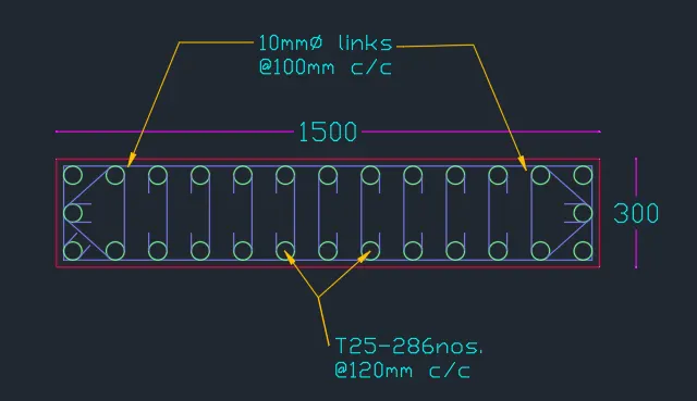
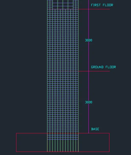
DETAILING FROM THE FIRST FLOOR TO THE TERRACE LEVEL
The boundary element demand reduces to 300mm. So, we can adapt the boundary element of 300mm on either side of the wall in this section running from the first floor to the terrace level.
Design of the Web Steel
Web width = 900mm
Minimum reinforcement ratio for the web as per IS-13920:2016 = 0.0025
Adopting 0.0030 for the safer calculations.
Ag = 900 x 300 = 270000
Asc = 0.0030 x 270000 = 810 sq.mm
Provide 6 bars of 16mm diameter = 6 x 201 = 1206 > 810 Hence OK.
Design of Boundary Element
Minimum Reinforcement Ratio as per the code = 0.008
Boundary Width = 300 mm
Ash = 0.05 Sv h fck/fy
As we have used 10mm dia stirrups@150mm c/c, Ash = 78.4mm2
Sv = 100mm for boundary element As per Clause 10.4.4
fck = 25
fy = 500
Therefore, h = 314mm.
Reinforcement required = total Ast - Ast taken by the Web = 4896 - 810 = 4086 sq.mm
Now, there are two boundary elements. So, Ast required for one BE = 4086/2 = 2043 sq.mm
Thus, provide 7 bars of 25mm diameter
Ast provided = 7 x 490 = 2940 > 2043 Hence OK.
Reinforcement ratio check:
ρ = Ast/bw.tw = 2940/300x300 = 0.032 > 0.008 Hence OK.
NOTE: We have carried 14 bars of 25mm diameter from the floor below satisfying the 50% lapping condition at one go.
RESULT
The values of longitudinal steel ratio, boundary element length, and shear reinforcing ratio from the design results have been extracted successfully. The cross-sectional steel arrangement of the shear wall from its base up to the terrace, in compliance with provisions of IS 13920:2016, has been drafted. The elevation drawings of reinforcement details of the shear wall from base to terrace have also been drafted. The results of each drawing drawn in ETABS and AutoCAD are attached.