Analog Control System
AIM: To study the Analog control system.
OBJECTIVES -
1. Answer the following-
a.) Compare analog control systems with digital ones with respect to electric vehicle motors.
b.) Explain callback and over-the-air update events by automotive companies.
2. Using MATLAB, plot bode diagram of a transfer function (second and third-order transfer functions to be considered) in s-domain and z-domain. Comment on the results.
3. Explain the process of the sample and hold technique in Simulink.
a.) With the help of a “sample and hold” block from the library browser.
b.) Obtain similar results without using the built-in sample and hold block.
OBJECTIVE 1 -
1. Answer the following-
a.) Compare analog control systems with digital ones with respect to electric vehicle motors.
b.) Explain callback and over-the-air update events by automotive companies.
a)Compare analog control systems with digital ones with respect to electric vehicle motors.
Analog deals, processes, and outputs continuous signals in a certain range. It is always progressively changing, whereas digital uses binary language for all sorts of computations, and thus it is either on or off with no in-betweens
- Digital control systems are more efficient overall and have duty cycle control to reduce/increase the circulating current in the case of change in load
- Easy to switch between linear and non-linear control
- Lesser fluctuations in load current and output voltage as digital control has a higher speed response to adjust and control accordingly.
- Various converter topologies can be supported - to implement a 4 quadrant DC/DC converter the entire circuit would need to be changed with analog control, but with digital it only requires a change in the program
- Analog circuits age over time, along with components such as chemically filled capacitors. With digital, control systems are more reliable as the only things that need to be checked/maintained are actuators and sensors.
- Higher switching frequency possible with digital controllers
- Digital controllers are intelligent and can make decisions in real-time using logic.
b.) Explain callback and over-the-air update events by automotive companies.
'Callback' was used until a few years ago, where if there's a problem with the car, the servicing/after-sales part of the company will call the customer to bring the car back and fix it in person.
Over the air (OTA) is a new approach that allows companies to fix the problem remotely. Updating software, fixing bugs, security fixes, etc can be done digitally. Vehicles nowadays are essentially computers on wheels, so all these updates can be done computer-to-computer.
These days, components are controlled through software instead of mechanical components. The vehicle has become intelligent and smart, and the Electronic Control Unit (ECU) has become one of the most important components in the vehicle today. The things that can be controlled remotely today as opposed to a decade ago are:
- Engine transmission can be turned on/off
- Passengers or the drivers can be locked inside the car
- Blowing the horn continuously
- Controlling the steering system
- Car braking system
- Speeding the car beyond road regulation.
- Controlling the navigation, audio, or infotainment system
- False alarm in the cockpit
These can be extremely helpful and protect the consumer if the car is stolen, for instance. It also helps to make driving a much more safe activity.
OBJECTIVE 2 - Using MATLAB, plot bode diagram of a transfer function (second and third-order transfer functions to be considered) in s-domain and z-domain. Comment on the results.
clc
clear all
close all

G1 = tf([3 2],[1 7 6])
Gz1 = c2d(G1,0.1)

G2 = tf([1 1],[1 3 12 -16])
Gz2 = c2d(G2,0.1)

figure(1)
bode(G1)
hold on
bode (Gz1)

figure(2)
bode(G2)
hold on
bode(Gz2)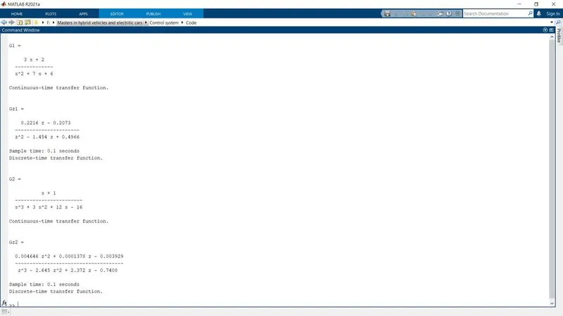
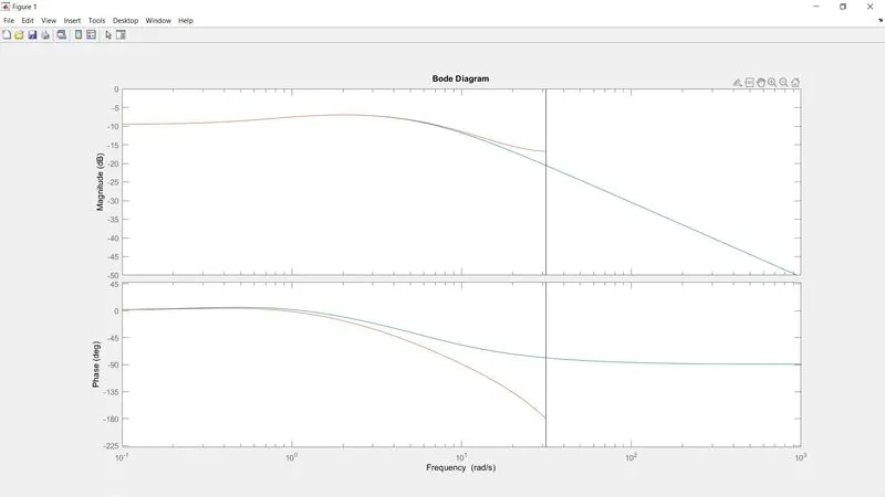
G1, G1z: Second order TF
G2, Gz2:Third order TF
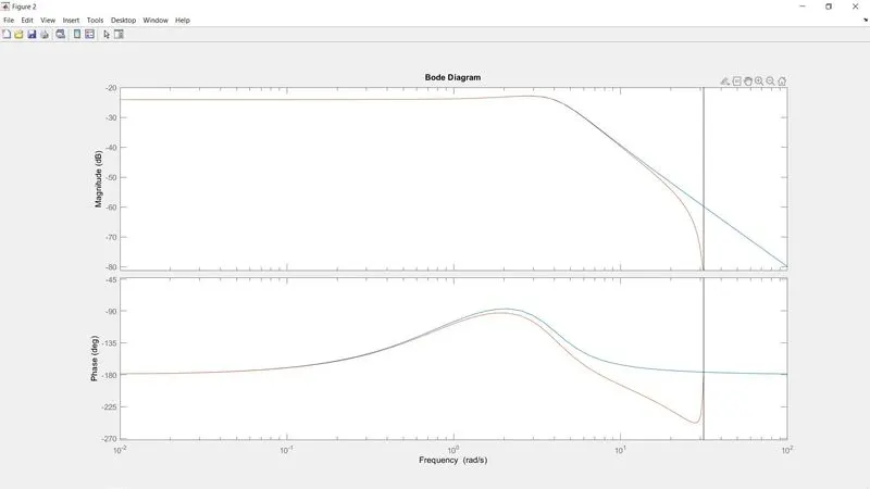
- Blue represents s-domain, orange represents z-domain
- In both functions, it is evident that until a certain frequency, the s and z domain completely overlap and give almost identical results.
- However, at higher frequencies, there is a clear difference in their responses. This is due to the conversion from continuous (s-domain) signal to discrete (z-domain), where a low sampling time is crucial. The current sampling time is 0.1, but the frequency to take samples must be higher (which means sampling time should become lower) to enable accurate conversion to z-domain.
Lowering sampling time from 0.1 to 0.01
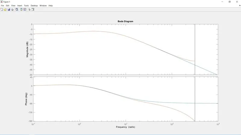
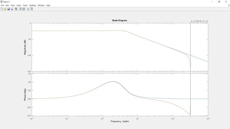
- Lowering the sampling time by 10x has made quite a difference, and more importantly has shown the importance of taking higher samples when converting from analog (continuous, s-domain) to digital (discrete, z-domain)
- The overlap is better, especially with the second-order TF. As the function becomes of higher-order, in this case, the third-order TF, even lower sampling time would be needed since the function has more variables and is more complicated.
OBJECTIVE 3 -
Explain the process of the sample and hold technique in Simulink.
a.) With the help of a “sample and hold” block from the library browser.
b.) Obtain similar results without using the built-in sample and hold block.
a.) With the help of a “sample and hold” block from the library browser.
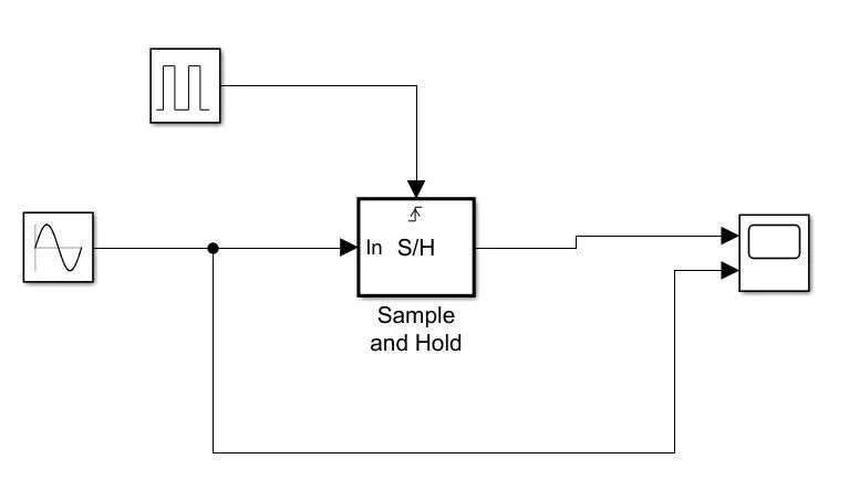
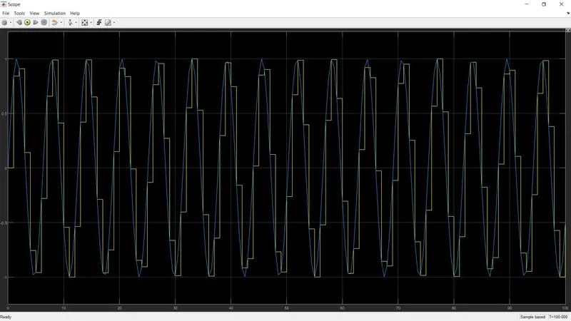
As we can see that the sine wave signal and the pulse generator signal are almost overlapping to each other, using the sample and hold block this is the output that we encounter. We were not able to completely convert the analog to a digital signal using the particular sample and hold technique, but we were able to convert some part of the signal to digital.
b.) Obtain similar results without using the built-in sample and hold block.
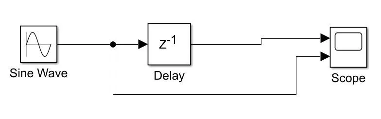
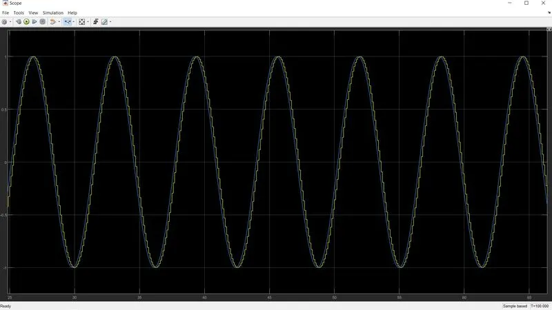
Now we will be using the delay block to convert the analog to digital output. As we can see the output of this system is much more accurate and we are able to exactly convert the sine signal to the analog signal.
CONCLUSION
Here we have understood the difference the analog and digital signals. Ploted the bode plot for the second and third-order transfer function system and compare the difference. we successfully saw the two different methods for the conversion of the analog to a digital signal.