Air standard Cycle
clear all
close all
clc

% defining engine parameters
bore=0.1;   % in meters
stroke=0.1;  % in meters
cr=12;
cond_rod=0.15;  % in meters

% defining state variables
p1=103125;  % in pascal
t1=500;  % in Kelvin
gamma=1.4;
t3=2300;  % in Kelvin

% 1-2 Isentropic compression
v_swept=(pi/4)*bore^2*stroke;
v_clearance=v_swept/(cr-1);

v1=v_swept+v_clearance;
v2=v_clearance;

% to find  state variables at point 2(p2 & t2).
p2=p1*(cr)^gamma; % p2v2^gamma=p1v1^gamma, p2=p1*(v1/v2)^gamma
t2=p2*v2*t1/(p1*v1); %(( P1v1)/T1)=((p2v2)/T2)

V_compression=engine_kinematicfunc(bore,stroke,cond_rod,cr,180,0);
c=p1*v1^gamma; % c=constant.
P_compression=c./(V_compression.^gamma);

% 2-3 constant volume heat addition(state variables at point 3)
v3=v2;
p3=(p2*t3)/t2;

V_expansion=engine_kinematicfunc(bore,stroke,cond_rod,cr,0,180);
c=p3*v3^gamma; %c=constant
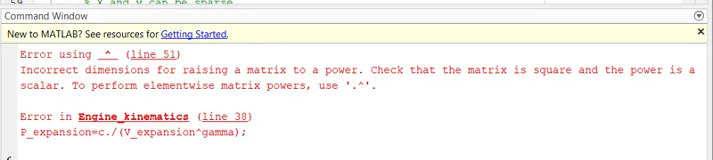
P_expansion=c./(V_expansion.^gamma);


% 3-4  expansion (state variables at point 4)
v4=v1;
p4=p3*(v3/v4)^gamma;
t4=p4*v4*t3/(p3*v3);

% to find efficiency
E=1-((cr)^(1-gamma)); % E=1-(t1/t2);E=thermal_efficiency

% points marking
figure(1)
hold on
plot(v1,p1,'*','color','r')
plot(V_compression,P_compression)
plot(v2,p2,'*','color','b')
plot([v2 v3],[p2 p3])
plot(v3,p3,'*','color','y')
plot(V_expansion,P_expansion)
plot(v4,p4,'*','color','k')
plot([v4 v1],[p4 p1])
xlabel('Volume')
ylabel('Pressure')
title('P-V Diagram for Otto Cycle')
legend('P1V1','Reverse adiabatic compression of Air','P2V2','Heat addition at constant VOlume','P3V3','Reversible adiabatic expansion of Air','P4V4','Heat rejection at constant Volume')

% Function code:

function [V]=engine_kinematicfunc(bore,stroke,cond_rod,cr,start_crank,end_crank)

a=stroke/2; % a=Crank pin radius
R=cond_rod/a; % R=Ratio of length of connecting rod to crank pin radius.

v_s=(pi/4)*bore^2*stroke;
v_c=v_s/(cr-1);

theta=linspace(start_crank,end_crank,180);

term1=0.5*(cr-1);
term2=(R+1-cosd(theta));
term3=((R^2-(sind(theta)).^2).^0.5);

V=((1+term1*(term2-term3)).*v_c);
end
Program Explanation:
1.'clear all' command used to clear the data stored in the workspace,'close all' command is used to close all the plots and figures and 'clc' command is used to clear the window
2.we enter the known/given inputs values,p1,t1,t3,gamma.
3.then the engine Geometric parameters are entered,bore dia,stroke length,connecting rod lenght and compresiion ratio.
4.The Swept volume and clearance volume is calculated by using formulas with known relations.
5.The state variables v1,v2,p2,t2,v3,p3,v4,p4 and t4 caculated by using formulas with known engine reations
6.A separate code is written to achieve a set of soln for every vlue of crank angle.
7.To compute this array the formulas for a, R,Vs and Vc are entered.
8.the valuse of crank angle 'theta'is calculated for 180 values between initial angle and final angle
9.P_compression,V_compression,P_expansion and V_expansion is calculated with respect to the crank angle 'theta'.
10.The Thermal efficiency is calcuted by known formula
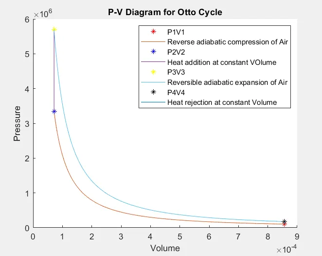
11.plotted the all variables points along with curves and PV cycle is obtained.
ERROR:
WORKSPACE:
PLOT:
Result:
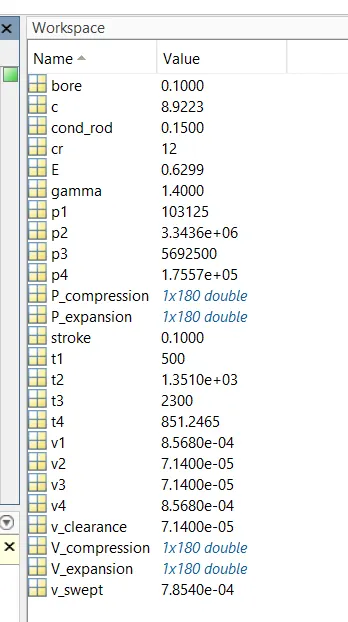
1.the thermal efficiency of the air standard cycle is 62.99 % . The Thermal efficiency is mainly depends on the compression ratio and type of fluid.
2.The PV diagram for all four process are plotted.