Ahmed Body Challenge
Aim: The aim of the given challenge is to perform external flow simulation over a Ahmed Body and refine the mesh as fine as possible to get accurate results for various physical properties.
Ahmed Body: The Ahmed Body was first created by S.R. Ahmed in his research “Some Salient Features of the Time-Averaged Ground Vehicle Wake” in 1984. Since then, it has become a benchmark for aerodynamic simulation tools. The simple geometrical shape has a length of 1.044 meters, height of 0.288 meters, and a width of 0.389 meters. It also has 0.5-meter cylindrical legs attached to the bottom of the body and the rear surface has a slant that falls off at 40 degrees.
Why Study the Drag Coefficient in Cars?
The drag coeffcient quantifies the resistance of an object in a fluid environment. It is not an absolute constant for a body’s shape because it varies with the speed and direction of flow, object shape and size, and the density and viscosity of the fluid. The lower the drag coefficient of an object, the less aerodynamic or hydrodynamic drag occurs. In terms of a car, the lower the drag coefficient, the more efficient the car is. As well as affecting the top speed of a vehicle, the drag coefficient also affects the handling. Cars with a low drag coefficient are sought after, but decreasing the drag drastically can reduce the downforce and lead to loss in road traction and a higher chance of car accidents.
Modeling Airflow Over an Ahmed Body
In the verification model of flow over a Ahmed Body, our Ahmed body is placed in the domain, measuring to compute the flow field.The front of the body is placed at a distance of 2 m from the flow inlet. To reduce the computational cost, a symmetry plane is introduced to model half of the model. The flow for this model is turbulent, which is based on the Reynolds number determined by the body length and inlet velocity. The simulation solves for the turbulent kinetic energy in addition to the velocity field. For this simulation, we need a larger mesh size than what is usually common to resolve the turbulent flow. More specifically, we use a finer mesh downstream of the model to capture the wake zone.
Gemoetry:
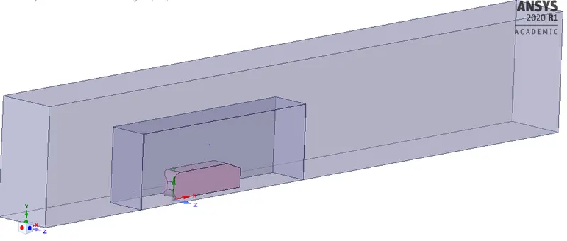
The geometry for Ahmed body is provided which is modified using spaceclaim for our simulation need.We have made two enclosures for the given geometry the external enlcosure and the inner enclosure just around the geometry of Ahmed Body.The external enclosure is provides us to capture the incoming flow variation and the inner enclosure allows us to generate much finer tetrahedral meshing to capture the flow over the geometry and the wake region more accuarately. This way we reduce the cell size more effciently.
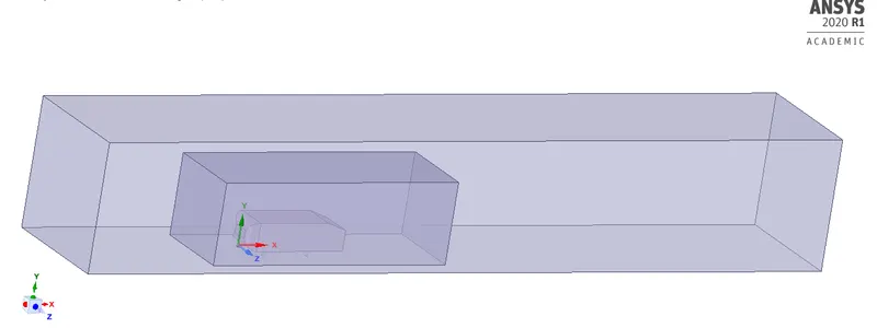
Cutplane: The given geometry is introduced with symmetrical cutplane in order to model only half of the geometry to reduce time and computational power.we use the command split mody in toolbar to cut the geometry in half.The hamed body is then suppresed for physics af we only need to simulate flow over the geometry and not inside it.
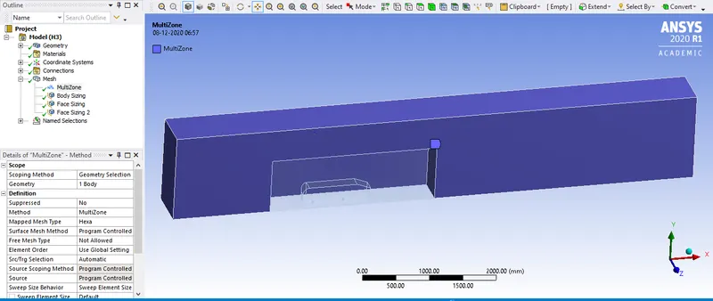
Meshing: The meshing of the given model is quite different then what i have done till now as we have employed two different meshing method for both enclosures. The The outer enclosure is meshed using multizone method that produces evenly spready hexahedral mesh whereever possibel. we are using multizone methos in this case as our geometry is perfectly hsaped and has no curves or uneven structures involved.
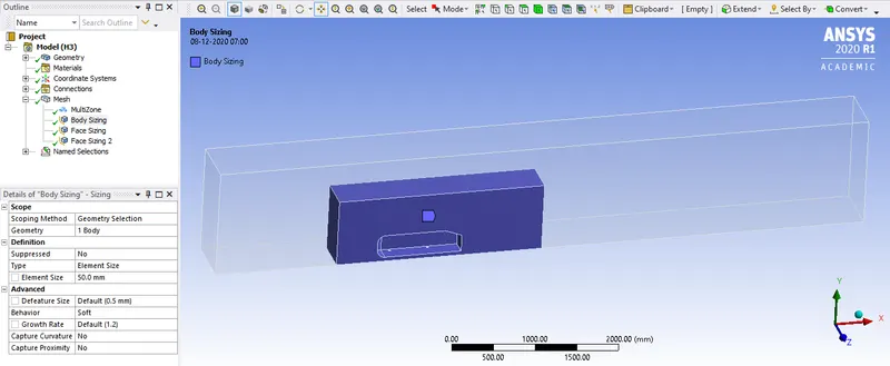
The inner enclosure is meshed using simple tetrahedral meshing with element size of 50mm. it generated more finer meshing around the geometry.
The bottom side of the Ahmed body consists of cylindrical geometry which is further need to given finer mesh size as it shows inperfect geometry with cuurent mehing size of 50 mm. hence we further use mesh sizing method and mesh only the cylindrical legs of geometry with mesh size of 2 mm.
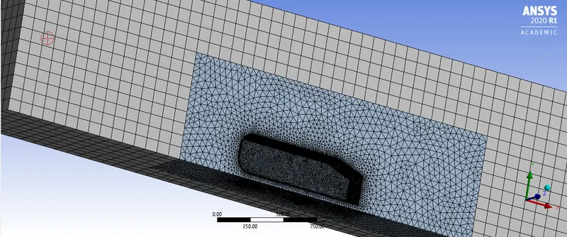
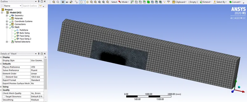
Further we generate Named selections for the inlet outlet symmetry wall and carbody/ahmed body for the geometry.
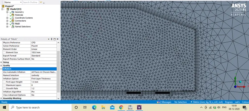
Inflation layer: Inflation layer is provided at the boundary of Ahmed Body with 6 layers of inflations. we have total thickness value on account of the y+ value. The y+ value gives the estimated wall disctance that i have determined by using following link
https://www.cfd-online.com/Tools/yplus.php
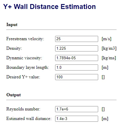
So the first layer thickness/ height is 1.4mm for the inflation layer with growth rate of 1.2.
Solution setup:
Enery equation is turned on and We have employed standard K-Epsilon turbulance model for our simulation as flow is turbulent.The model captured turbulace better not only at the wall but also at the bounadries.
Material: We have used air as standard material as medium of flow and have made no change in property
Boundary conditions: For inlet we have flow at velocity of 25m/s and outlet at 1 atm pressure.For walls we have symmetry boundary conditions.
The solution method:
we have chosen pressure based solver under steady state hybrid initialization.
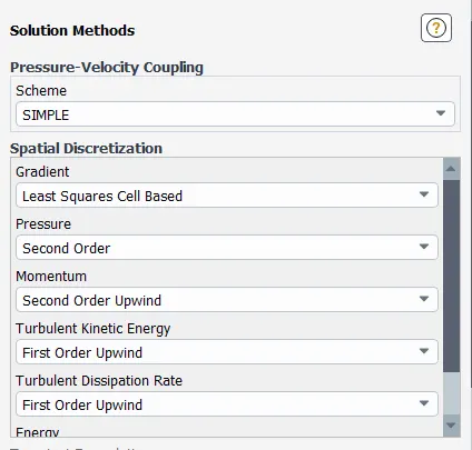
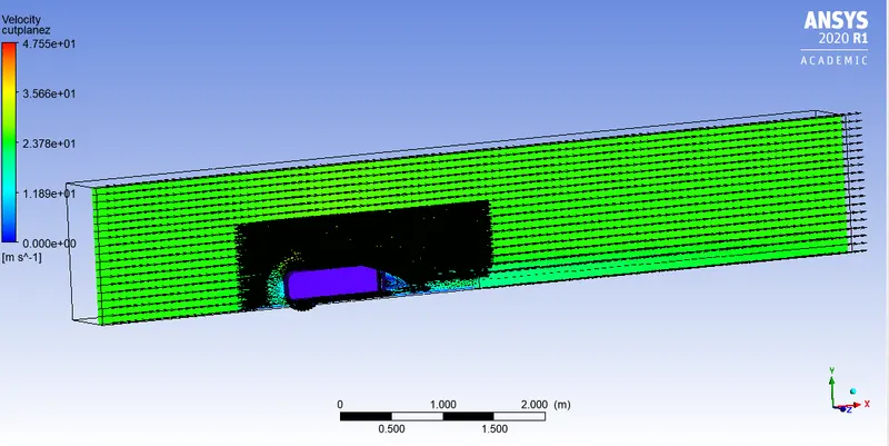
We compute velocity and pressure contours, lift and drag coeffcient, vector plot with wake region and residual plot.
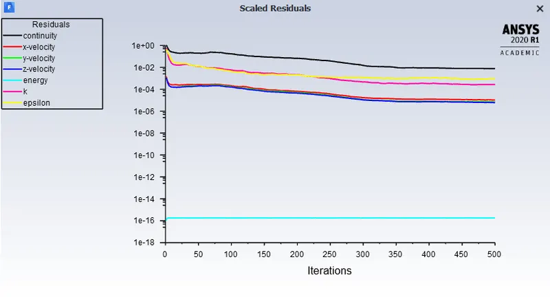
Residual value:
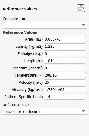
Case 1) with mesh size 100 mm(outer closure) and 50mm(inner closure)
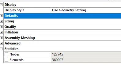
Results:
Residual plot:
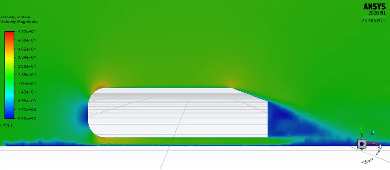
Velocity Contour:
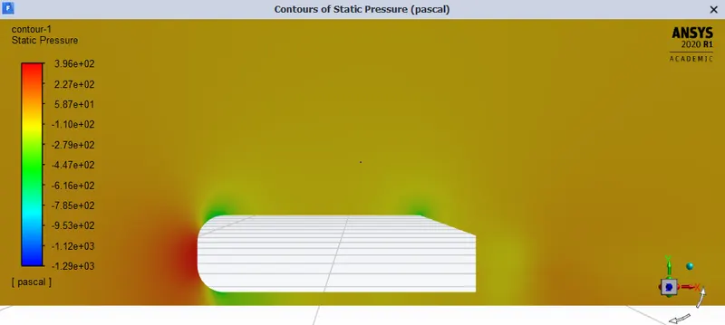
Pressure contour:
Drag coeffcient:
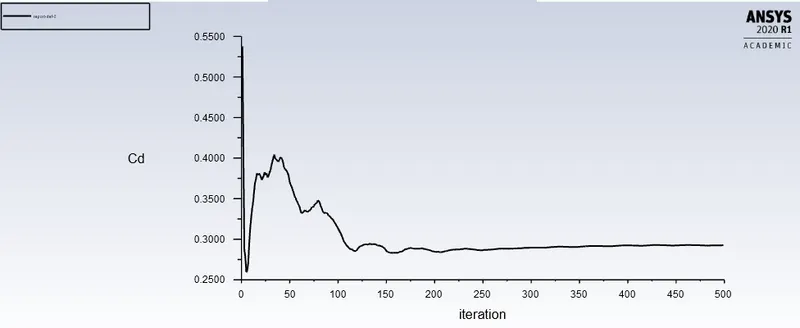
Drag coeffcient is 0.29254835
Lift coeffcient:
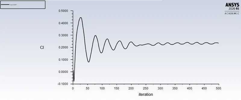
Lift coeffcient is 0.23311543
Velocity Vector plot :
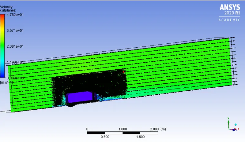
Case 2) with mesh size 90 mm(outer closure) and 45mm(inner closure)
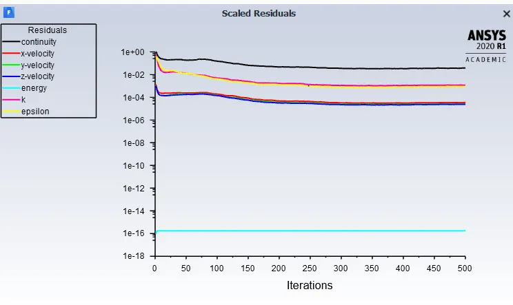
Residual Plot:
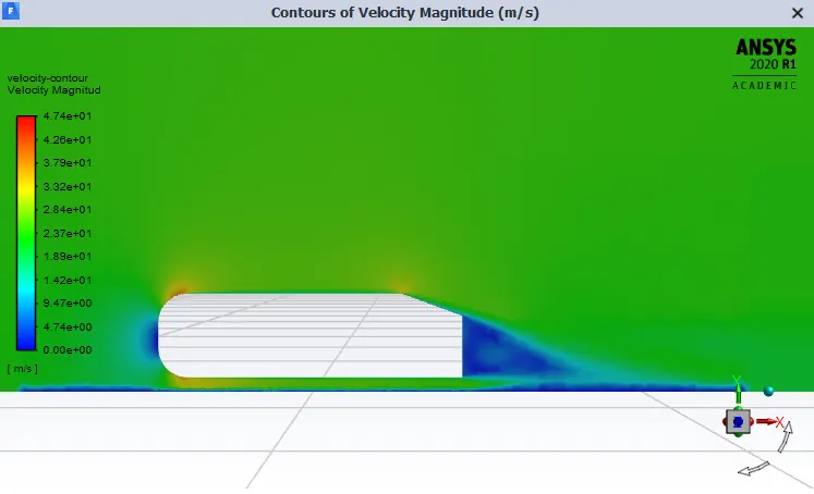
Velocity Contour:
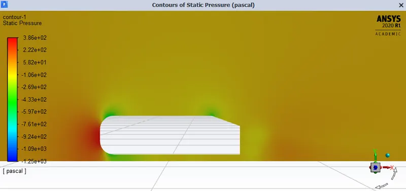
Pressure contour:
Drag Coeffcient:
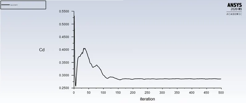
Coeffcient of drag is 0.2856783
Coeffcient of lift:
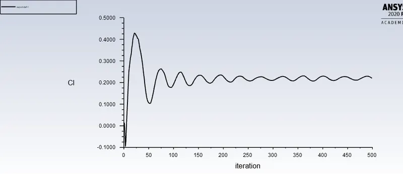
Coeffcient of Lift is 0.2184924
Velocity Vector plot:
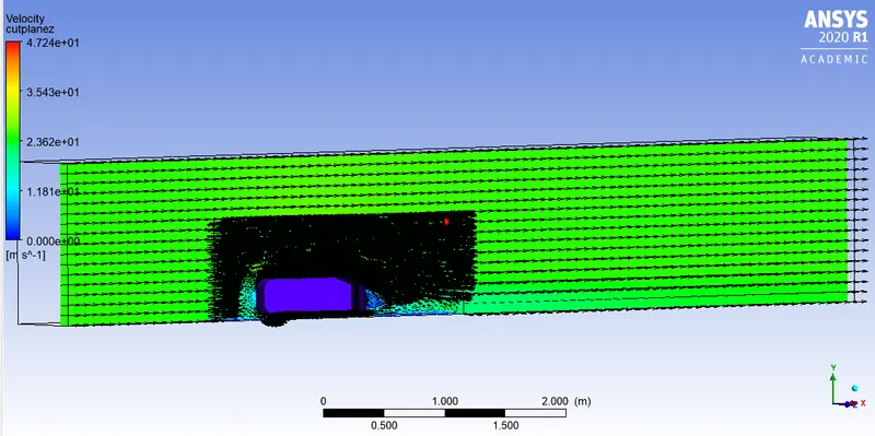
Case 3) with mesh size 80 mm(outer closure) and 40mm(inner closure)

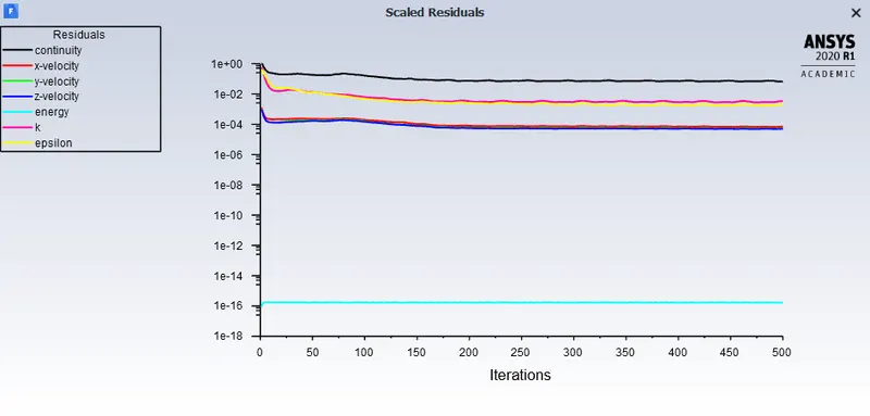
Residual Plot:
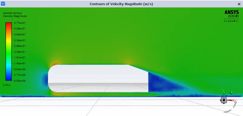
Velocity contour plot:
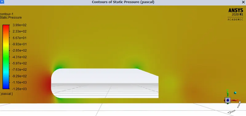
Pressure contour plot:
Drag coeffcient:
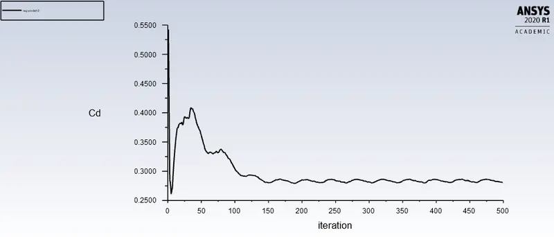
The coeffcient of drag is 0.28142849
Lift Coeffcient:
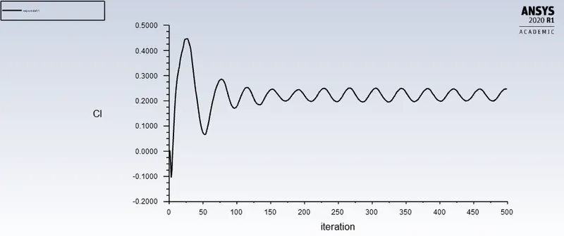
Coeffcient of lift is 0.24452574
Velocity vector plot:
Conclusion:
1) Negative pressure drop in wake region is visible in all of our pressure contour plots, the reason for this is a wake region is formed at the rear side of the Ahmed body as flow seperation occures at this region and vaccum is formed.The flow seperation at the rear of the body causes formation of wake region that contibutes to negetive pressure drop.
2)Flow separation or boundary layer separation is the detachment of a boundary layer from a surface into a wake Separation occurs in flow that is slowing down, with pressure increasing, after passing the thickest part of a streamline body or passing through a widening passage.
3) Point of seperation: The separation point is the point where the air stops "sticking" to an object that is moving through the air. When an object is moving through the air, the air molecules push back on it and resist the object's movement - this resistance is called pressure drag. As the air flows around the object, it "sticks" to the object, forming what is known as the boundary layer. This "attached flow" is flowing very smoothly. The point on the body where the boundary layer lifts off the surface is called the separation point. When the air flow separates off the surface, the pressure drag usually increases.
Results:
The grid independence test gives following tabulated results for coeffcient of liftand drag
|
Sr.no |
Mesh size Inner/Outer Enclosure |
Number of Elements |
Coefficient of Drag |
Coefficient of Lift |
|
1 |
100/50 mm |
380207 |
0.29254835 |
0.23311543 |
|
2 |
90/45 mm |
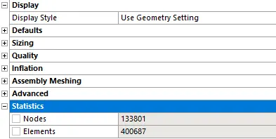
400687 |
0.2856783 |
0.2184924 |
|
3 |
80/40 mm |
435246 |
0.28142849 |
0.24452574 |
The coeffcient of drag goes on decresesing when we use larger number of cells and more refined mesh size, where else the coeffcient of lift goes on incresesing.The mesh size of 380207 elements gives us more accurate results for drag coeffcient that is expected.