Aerofoil stall aerodynamics in OpenFOAM
OBJECTIVE: To perfrom aerofoil stall aerodynamic simulation for NACA6409 in OpenFOAM.
THEORY:
DRAG
Drag is a mechanical force. It is generated by the interaction and contact of a solid body with a fluid. For drag to be generated, the solid body must be in contact with the fluid. If there is no fluid, there is no drag. Drag is generated by the difference in velocity between the solid object and the fluid. There must be motion between the object and the fluid. If there is no motion, there is no drag. We can think of dragas aerodynamic friction, and one of the sources of drag is the skin friction between the molecules of the air and the solid surface. We can also think of drag as aerodynamic resistance to the motion of the object through the fluid. This source of drag depends on the shape of the object.
LIFT
Lift is the force that directly opposes the weight of an object and holds the object in the air. Lift acts through the centre of pressure of the object and is directed perpendicular to the flow direction. There are several factors which affect the magnitude of lift. Lift is majorly due to the pressure distribution on the surface of the object. It is said that there are two theories behind generation of lift, one which says that lift is generated due to difference in velocity of fluid above and below the object the other says that it is generated due to newtons 3rd law by which upwash and downwash are created which generate lift.
STALL
A stall is a reduction in the lift coefficient generated by a foil as angle of attack increases. This occurs when the critical angle of attack of the foil is exceeded. The critical angle of attack is the angle of attack which produces the maximum lift coefficient. This is also called the "stall angle of attack". Below the critical angle of attack, as the angle of attack decreases, the lift coefficient decreases.
LAMINAR FLOW
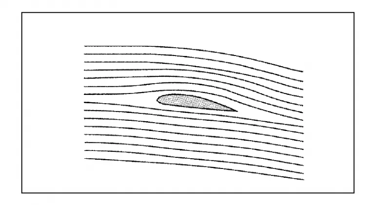
Stream line flow is some times called laminar flow. In other words, a flow which maintains the shape of the body over which it is flowing (Figure) is the laminar flow.
TURBULENT FLOW
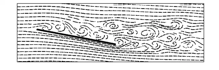
This is a flow in which the fluid particles may move perpendicular as well as parallel to the surface of the body and undergo eddying or unsteady motions. This may result in considerable thickening of the airflow and lead to break-up.
AEROFOIL TERMINOLOGY
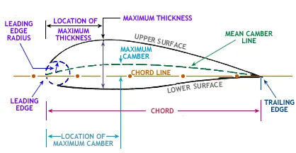
Chord is a distance between the leading and trailing edges measured along the chord line.
Chord line is a straight line joining the leading and trailing edges of an aerofoil.
Leading edge is a part of an aerofoil (edge) that hits the air particles first.
Lower surface is the surface of an aerofoil between the leading and trailing edges, on the lower surface.
Mean camber line is a line joining the leading and trailing edges of an aerofoil, equidistant from the upper and lower surfaces.
Maximum camber is the maximum distance of the mean camber line from the chord line.
Maximum thickness is the maximum distance of the lower surface from the upper surface.
Trailing edge is a part from an aerofoil (edge) that hits the air particles last.
Upper surface is the surface of an aerofoil between the leading and trailing edges, on the upper surface.
ANGLE OF ATTACK
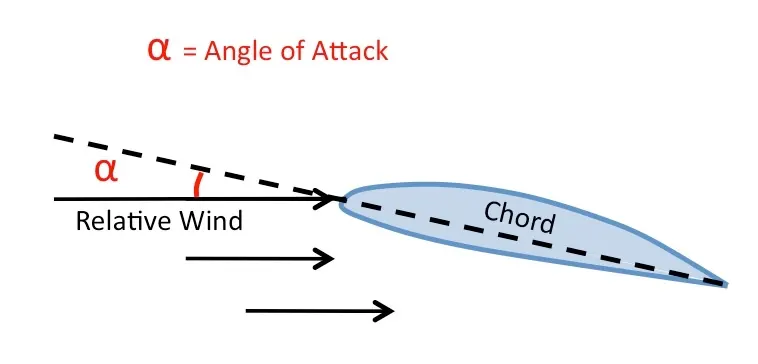
The Angle of Attack is the angle at which relative wind meets an aerofoil. It is the angle formed by the Chord line of the aerofoil and the direction of the relative wind or the vector representing the relative motion between the aircraft and the atmosphere.
SUBSONIC AND SUPERSONIC FLOW
Flow of air with the speed below sonic speed is called subsonic flow and that with the speed in the supersonic range is called the supersonic flow.
Airflow at subsonic range is treated as incompressible flow while at supersonic range it is treated as compressible flow.
EFFECT OF FLOWPATTERN OVER OBJECTS
Flow pattern over an object especially the aerodynamically designed objects (e.g. wings of an aeroplane) has very important effect. Aerodynamic reaction for producing desired lift forces with minimum unwanted drag forces is the prime objective of aerodynamically shaping the wings and other aerodynamic surfaces. Properly shaped objects that ensures flow over it is laminar/streamlined is called streamlined object and the stream line flow over such objects (e.g. wings) has the contribution towards producing lift, while the cross flow creating turbulence destroys lift and produces more drag which is an evil for most part of the flight.
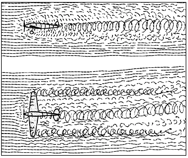
If air could have been seen as shown Figure, these air patterns of wakes and turbulences created by edges and corners of flying objects in the air. These patterns are creating huge obstructions in the form of drag forces to be imposed as loads for engine thrusting the aircraft forward with so much penalty of extra fuel burn.
Besides, these drag produced on the aircraft because of its drag by the wakes and turbulences, stalling of wings may happen due to turbulence over wings resulting in the loss of lift forces.
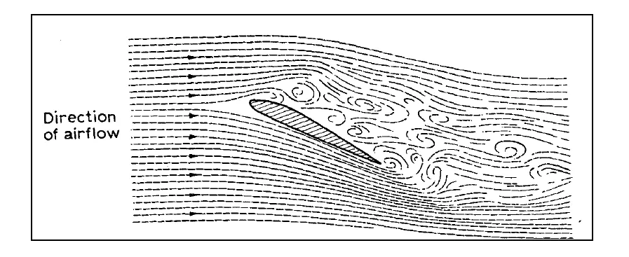
BOUNDARY LAYER AND ITS CONTROL:
Control of boundary layer is very important for a flight.
The layer of air over a surface that is slower moving in relation to the rest of the fast moving slipstream is called the boundary layer.
Friction between the surface and the air particles does not permit the flow over the surface to attain the local free stream velocity immediately. The particle just over the surface has about the zero velocity, the next upward layer has little more than zero velocity and the next upward one has further more velocity. This variation in velocity continues until attaining the full velocity of the free air stream. Thus, there is a layer, adjacent to the surface, in the air stream where air velocity varies from ZERO to free stream velocity. This layer is the boundary layer.
Within the boundary layer, there exists relative velocity exist i.e. one upper layer slides over the adjacent lower layer; thus all the fluid friction (due to air viscosity) comes into play in the boundary layer. More the viscosity, more is the friction. More the boundary layer thickness more is the amount of frictional force that the body is to overcome to move forward.
The layers of air near the surface retard the layers farther away – owing to the friction between them, i.e. the viscosity – and so there is a gradual increase in velocity as the distance from the surface increases. The maximum velocity – that of the free airflow – is reached sooner over a smooth surface than over a rough one, and since it is the shearing action between the layers which causes the resistance it follows that a smooth surface will have less resistance than a rough surface. Over a smooth surface like that of a wing most of the increase in velocity may occur within a millimetre or so of the surface as compared with the few metres which we mentioned earlier in connection with an aerodrome surface.
Laminar Boundary Layer:The boundary layer can be termed as laminar when there is no cross flow of air particles between the layers.
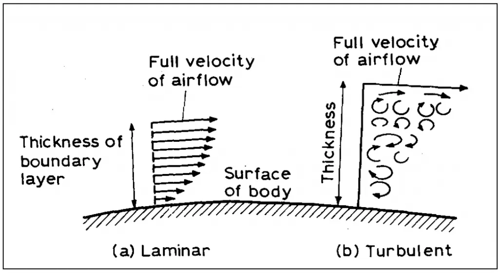
Turbulent Boundary Layer:The boundary layer can be termed as turbulent when there is cross flow of air particles between the layers. Due to lose of energy, flow first becomes wavy in transition and then grows into turbulence.
The usual tendency is for the boundary layer to start by being laminar near the leading edge of a body, but there comes a point, called the transition point, when the layer tends to break away from the surface and become turbulent and thicker (Figure). As the speed increases the transition point tends to move further forward, so more of the boundary layer is turbulent and the skin friction greater.
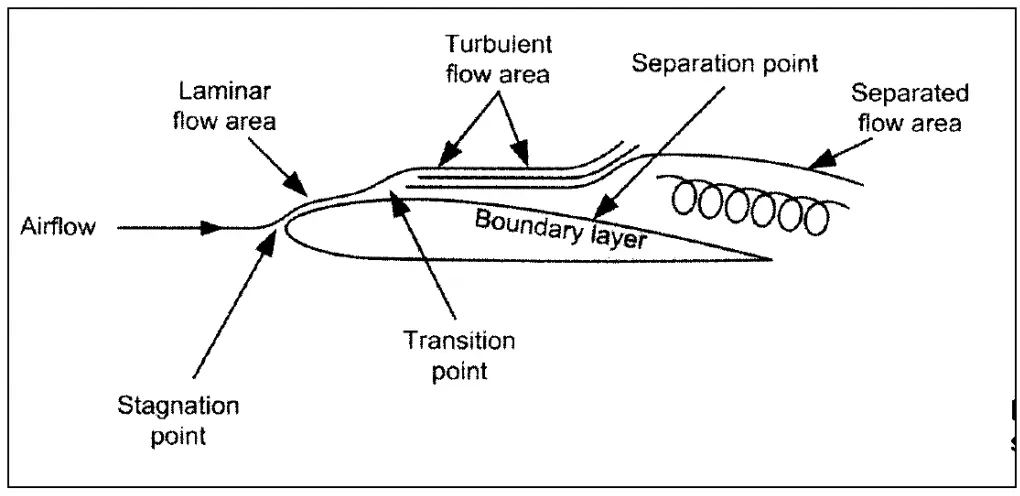
FORMATION AND DEVELOPMENT OF BOUNDARY LAYER
When a body such as an aircraft wing is immersed in a fluid, which is flowing past it, the fluid molecules in contact with the wings surface tend to be brought to rest by friction and stick to it. The next molecular layer of the fluid tends to bind to the first layer by molecular attraction but tends to shear slightly creating movement with respect to the first stationary layer. This process continues as successive layers shear slightly relative to the layer underneath them. This produces a gradual increase in velocity of each successive layer of the fluid (say air) until the free stream relative velocity is reached some distance away from the body immersed in the fluid.
For an aircraft, subject to laminar flow over its wing section, the thickness of the boundary layer is seldom more than 1 mm. The thinner the boundary layer, the less the drag and the greater the efficiency of the lift producing surface. Since friction reduces the energy of the air flowing over an aircraft wing, it is important to keep wing surfaces and other lift producing devices as clean and as smooth as possible. This will ensure that energy losses in the air close to the boundary are minimized and efficient laminar flow is maintained for as long as possible.
SHOCK WAVE FORMATION AND DEVELOPMENT
All the points on the surface of a wing produce pressure waves. If the airflow is subsonic, these pressure waves can all move away- ahead of the wing, but when the critical Mach Number is reached and the speed becomes sonic speed at some point on the wing, pressure waves move forward only as far as this point and then “pick-up” to form a Shock Wave.
If the speed is increased further the shock wave starts to move towards the trailing edge as the supersonic area above the wing grows larger. Another shock wave will form below the wing and will also move towards the trailing edge.
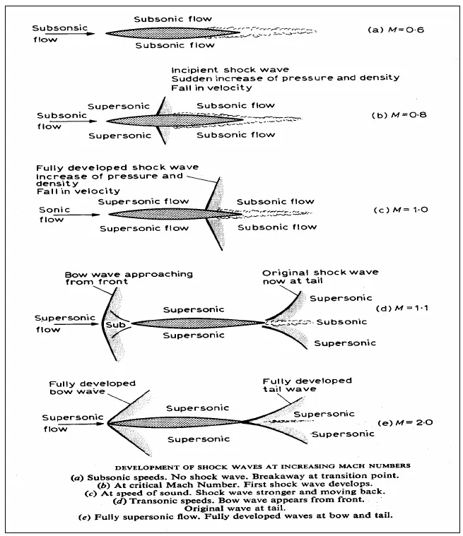
As the speed of the wing through the air is increased the wing shook waves move back towards the trailing edge and when the wing reaches sonic speed a Bow Wave forms ahead of the leading edge.
CASE SETUP:
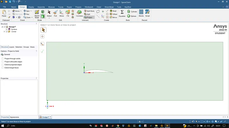
For this project aerofoil NACA6409 has been selected. The first step was to generate the geometry of the aerofoil with various angle of attacks, the range of angle of attack being tested in this project was set from -5 degress to 25 degree. The aerofoil profile was obtained using aerofoil generator available online, and using the co-ordinates of the foil we created 2D sketch of the aerofoil in ANSYS SpaceClaim by creating the curves. After which the created aerfoil was bounded by a rectangular box. The surface was generated out of this which will act as the control or fluid flow volume for this case.
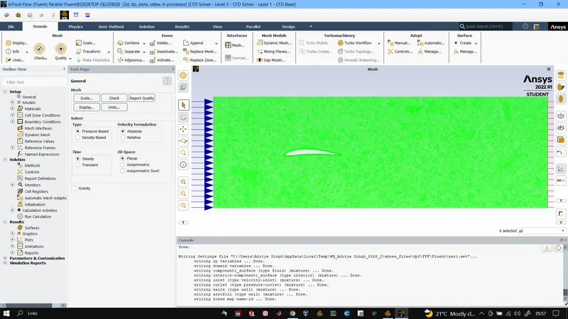
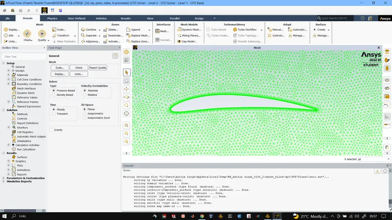
After this we created the mesh using ANSYS FLUENT mesh. The mesh was made to be triangle dominated and inflation layers were inserted on the aerofoil. After successful meshing of required quality the boundaries were named and the mesh was exported in ASCII format.
After exporting the mesh we went to OpenFOAM where we copied the example case from incompressible/simpleFoam/aerofoil2D and inserted our mesh export foil in it. After that the polymesh file was deleted and then fluentMeshToFoam command was used to convert the fluent mesh into openfoam polymesh file. After that changes were made to the p U nu contorldict files as per our requirement for the case setup.
Velocity Initial Conditions
/*--------------------------------*- C++ -*----------------------------------*
  =========                 |
        /  F ield         | OpenFOAM: The Open Source CFD Toolbox
       /   O peration     | Website:  https://openfoam.org
      /    A nd           | Version:  9
     /     M anipulation  |
*---------------------------------------------------------------------------*/
FoamFile
{
    format      ascii;
    class       volVectorField;
    object      U;
}
// * * * * * * * * * * * * * * * * * * * * * * * * * * * * * * * * * * * * * //

dimensions      [0 1 -1 0 0 0 0];

internalField   uniform (0 0 0);

boundaryField
{
    inlet
    {
        type            fixedValue;
        value           uniform (14.27 0 0);
    }

    outlet
    {
        type            zeroGradient;

    }

    walls
    {
        type            slip;
    }
    aerofoil
    {
        type            noSlip;
    }
    frontAndBackPlanes
    {
        type            empty;
    }
}

// ************************************************************************* //
Pressure Initial Conditions
/*--------------------------------*- C++ -*----------------------------------*
  =========                 |
        /  F ield         | OpenFOAM: The Open Source CFD Toolbox
       /   O peration     | Website:  https://openfoam.org
      /    A nd           | Version:  9
     /     M anipulation  |
*---------------------------------------------------------------------------*/
FoamFile
{
    format      ascii;
    class       volScalarField;
    object      p;
}
// * * * * * * * * * * * * * * * * * * * * * * * * * * * * * * * * * * * * * //

dimensions      [0 2 -2 0 0 0 0];

internalField   uniform 0;

boundaryField
{
    inlet
    {
        type            zeroGradient;

    }

    outlet
    {
        type            fixedValue;
        value           uniform 0;
    }

    walls
    {
        type            zeroGradient;
    }

    aerofoil
    {
        type            zeroGradient;
    }

    frontAndBackPlanes
    {
        type            empty;
    }
}

// ************************************************************************* //
nut Initial Condition
/*--------------------------------*- C++ -*----------------------------------*
  =========                 |
        /  F ield         | OpenFOAM: The Open Source CFD Toolbox
       /   O peration     | Website:  https://openfoam.org
      /    A nd           | Version:  9
     /     M anipulation  |
*---------------------------------------------------------------------------*/
FoamFile
{
    format      ascii;
    class       volScalarField;
    object      nut;
}
// * * * * * * * * * * * * * * * * * * * * * * * * * * * * * * * * * * * * * //

dimensions      [0 2 -1 0 0 0 0];

internalField   uniform 1.48e-4;

boundaryField
{
    inlet
    {
        type            fixedValue;
        value           uniform 1.48e-4;
    }

    outlet
    {
        type            zeroGradient;

    }

    walls
    {
        type            nutUSpaldingWallFunction;
        value           uniform 0;
    }

    aerofoil
    {
        type            nutUSpaldingWallFunction;
        value           uniform 0;
    }

    frontAndBackPlanes
    {
        type            empty;
    }
}

// ************************************************************************* //
Transport properties
/*--------------------------------*- C++ -*----------------------------------*
  =========                 |
        /  F ield         | OpenFOAM: The Open Source CFD Toolbox
       /   O peration     | Website:  https://openfoam.org
      /    A nd           | Version:  9
     /     M anipulation  |
*---------------------------------------------------------------------------*/
FoamFile
{
    format      ascii;
    class       dictionary;
    location    "constant";
    object      transportProperties;
}
// * * * * * * * * * * * * * * * * * * * * * * * * * * * * * * * * * * * * * //

transportModel  Newtonian;

rho             [1 -3 0 0 0 0 0] 1.225;

nu              [0 2 -1 0 0 0 0] 1.78e-05;

// ************************************************************************* //
Momentum Transport
/*--------------------------------*- C++ -*----------------------------------*
  =========                 |
        /  F ield         | OpenFOAM: The Open Source CFD Toolbox
       /   O peration     | Website:  https://openfoam.org
      /    A nd           | Version:  9
     /     M anipulation  |
*---------------------------------------------------------------------------*/
FoamFile
{
    format      ascii;
    class       dictionary;
    location    "constant";
    object      momentumTransport;
}
// * * * * * * * * * * * * * * * * * * * * * * * * * * * * * * * * * * * * * //

simulationType RAS;

RAS
{
    model           SpalartAllmaras;

    turbulence      on;

    printCoeffs     on;
}

// ************************************************************************* //
Control Dict
/*--------------------------------*- C++ -*----------------------------------*
  =========                 |
        /  F ield         | OpenFOAM: The Open Source CFD Toolbox
       /   O peration     | Website:  https://openfoam.org
      /    A nd           | Version:  9
     /     M anipulation  |
*---------------------------------------------------------------------------*/
FoamFile
{
    format      ascii;
    class       dictionary;
    location    "system";
    object      controlDict;
}
// * * * * * * * * * * * * * * * * * * * * * * * * * * * * * * * * * * * * * //

application     simpleFoam;

startFrom       startTime;

startTime       0;

stopAt          endTime;

endTime         1000;

deltaT          1;

writeControl    timeStep;

writeInterval   10;

purgeWrite      0;

writeFormat     ascii;

writePrecision  6;

writeCompression off;

timeFormat      general;

timePrecision   6;

runTimeModifiable true;


// ************************************************************************* //
After setting up the complete case in OpenFOAM we ran simpleFoam solver on the case setup and then the results were post-processed in PARAVIEW.
Various filters were used to calculate lift and drag forces, first we used EXTRACT BLOCK filter to extract aerofoil from the volume then we used EXTRACT SURFACE filter to extract the surface from the extracted block on which we used GENERATE SURFACE NORMAL filter to generate the surface normals. After which we used the calculator filter to generate Lift and drag force on the aerofoil surface.
POST_PROCESSING RESULTS:
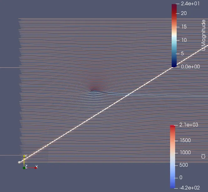
AoA 10 Degree
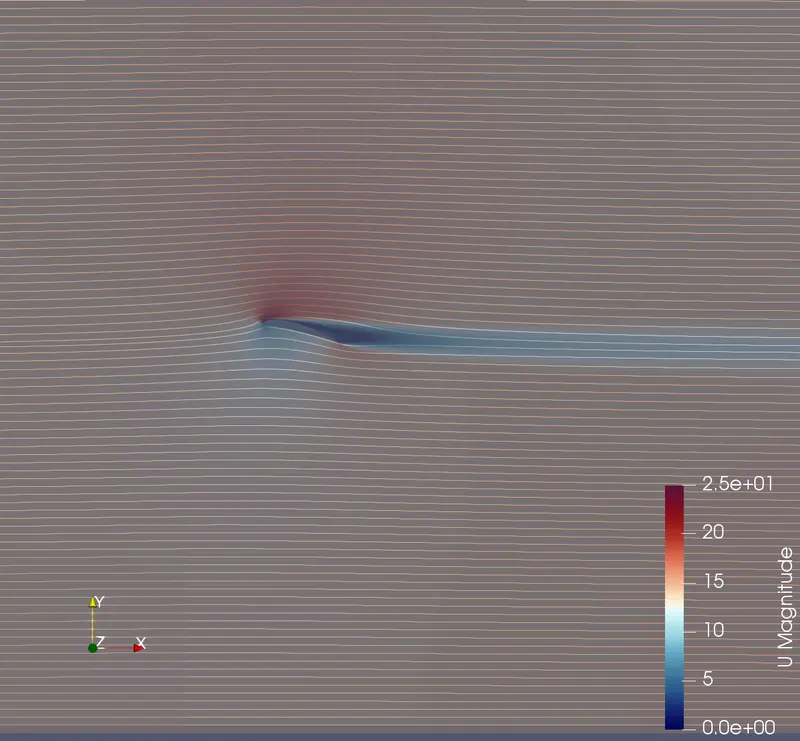
AoA 15 Degree
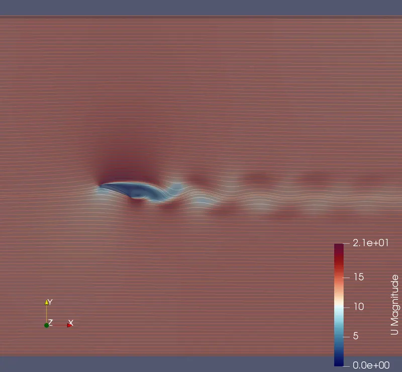
AoA 20 Degree
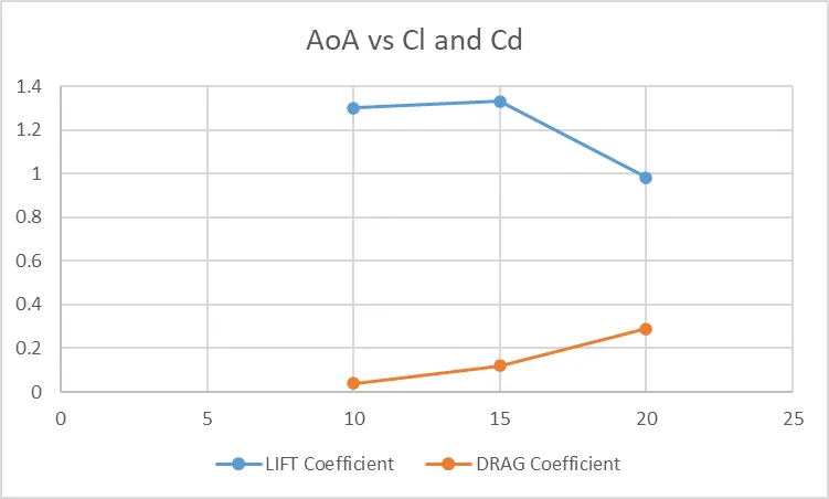
| AoA | LIFT Coefficient | DRAG Coefficient |
| 10 | 1.30056 | 0.040 |
| 15 | 1.33257 | 0.121 |
| 20 | 0.984 | 0.290 |
Refrence length = 0.04932m | Refrence Area = 0.000915 meter square.
CONCLUSION:
From the above graphs obtained it is clear that the drag force increases with the increase in the AOA (Angle of Attack).
At lower angle of attacks we observe formation of trailing edge vertices, as the angle of attack increases the separation point move towards the leading edge generating a shear layer whose origin follow the separation point and hence we observe kelvin-helmholtz rollers at moderate angle of attacks. As AoA gets even higher the sepration point reaches the leading edge hence forming the final shear layer the KH rollers of this layer forms the dynamic stall vortex.
The magnitude of the drag generated by an object depends on the shape of the object and how it moves through the air. For thin airfoils, the drag is nearly constant at small angles (+/- 5 degrees). As the angle increases above 5 degrees, the drag quickly rises because of increased frontal area and increased boundary layer thickness. As an object moves through the air, air molecules stick to the surface. This creates a layer of air near the surface called a boundary layer which, in effect, changes the shape of the object. The flow reacts to the edge of the boundary layer just as it would to the physical surface of the object. To make things more confusing, the boundary layer may lift off or "separate" from the body and create an effective shape much different from the physical shape.
The magnitude of the lift generated by an object depends on the shape of the object and how it moves through the air. For thin airfoils, the lift is directly proportional to the angle of attack for small angles (within +/- 10 degrees). For higher angles, however, the dependence is quite complex. As an object moves through the air, air molecules stick to the surface. This creates a layer of air near the surface called a boundary layer that, in effect, changes the shape of the object. The flow turning reacts to the edge of the boundary layer just as it would to the physical surface of the object.
At this point the trailing edde doesnt shed vortices, and at later stages we also observe the dynamic stall vortex being convected downstream.