Project-1: Powertrain for aircraft in runways
Search and list out the total weight of various types of aircrafts.
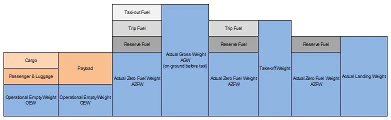
MAXIMUM DESIGN TAXI WEIGHT (MDTW OR MTW)
The maximum design taxi weight or maximum design ramp weight (MDRW) is the maximum certificated design weight for aircraft ground manoeuvres as limited by aircraft strength and airworthiness requirements.
MAXIMUM DESIGN TAKEOFF WEIGHT (MDTOW OR MTOW)
The maximum design take-off weight is the maximum certificated design weight for take-off run as limited by aircraft strength and airworthiness requirements.
MAXIMUM DESIGN LANDING WEIGHT (MDLW OR MLW)
The Maximum design landing weight is the maximum certificated design weight for landing limited by aircraft strength and airworthiness requirements. It generally depends on the landing gear strength or the landing impact loads on certain parts of the wing structure.
MDLW < MDTOW < MDTW
MAXIMUM DESIGN ZERO-FUEL WEIGHT (MDZFW)
The maximum design zero-fuel weight is the maximum certificated design weight of the aircraft less all usable fuel and other specified usable agents as limited by aircraft strength and airworthiness requirements.
MINIMUM FLIGHT WEIGHT (MFW)
Minimum certificated weight for flight as limited by aircraft strength and airworthiness requirements.
AIRCRAFT GROSS WEIGHT
The aircraft gross weight is the total aircraft weight at any moment during the flight or ground operation.
OPERATIONAL EMPTY WEIGHT (OEW)
The MEW and the operator’s items are summed up to the Operational Empty Weight (OEW). The OEW is usually fixed for a specific aircraft and only gets changed during maintenance or operational changes.

ACTUAL ZERO FUEL WEIGHT (AZFW)
If we add the payload to the empty plane weight, we get the Actual Zero Fuel Weight (AZFW).

ACTUAL GROSS WEIGHT (AGW)
In addition to the actual zero fuel weight, we add the fuel required for the flight and we get the Actual Gross Weight (AGW).

|
Aircraft |
Empty Weight |
Max Fuel Weight |
Max Cargo Weight |
Max Gross Takeoff Weight |
|
Antanov AN-225 |
628,000 lbs |
661,400 lbs |
417,000 lbs |
1,411,000 lbs |
|
Airbus A380-800 |
611,000 lbs |
560,000 lbs |
185,000 lbs |
1,268,000 lbs |
|
Boeing 747-800 |
485,300 lbs |
427,400 lbs |
295,000 lbs |
987,000 lbs |
|
Airbus A340-500 |
370,000 lbs |
386,300 lbs |
119,000 lbs |
820,000 lbs |
|
Boeing 777-300ER |
370,000 lbs 168,000 kg |
320,800 lbs 145,500 kg |
148,000 lbs |
776,000 lbs |
|
Boeing 787-10 |
299,000 lbs 135,500 kg |
223,500 lbs |
126,300 lbs 57,300 kg |
560,000 lbs |
|
Boeing 737-900 |
98,500 lbs |
53,100 lbs |
44,600 lbs |
187,000 lbs |
|
Airbus A320-100 |
93,900 lbs |
48,700 lbs |
44,000 lbs |
150,000 lbs |
|
Embraer 190 |
63,500 lbs |
28,600 lbs |
28,800 lbs |
106,000 lbs |
|
Gulfstream G650 |
54,000 lbs 24,500 kg |
48,200 lbs 21,900 kg |
6,500 lbs |
100,000 lbs |
|
Bombardier CRJ900 |
48,160 lbs 21,850 kg |
19,600 lbs 8,900 kg |
6,075 lbs 2,760 kg |
80,500 lbs |
|
Bombardier Q400 |
39,300 lbs |
11,700 lbs |
18,700 lbs |
62,000 lbs |
|
Learjet 75 |
13,900 lbs 6,300 kg |
6,060 lbs |
2,900 lbs |
21,500 lbs |
|
Cessna Citation CJ4 |
10,300 lbs 4,700 kg |
5,800 lbs |
2,200 lbs 1,000 kg |
17,200 lbs |
|
Beechcraft King Air B100 |
7,100 lbs 3,200 kg |
3,200 lbs |
4,150 lbs |
12,000 lbs |
|
Diamond DA50 RG |
3,200 lbs |
340 lbs |
1,250 lbs |
4,400 lbs |
|
Beechcraft Bonanza G36 |
2,500 lbs 1,150 kg |
450 lbs |
850 lbs |
3,660 lbs |
|
Cessna 206H |
2,200 lbs |
520 lbs |
1,150 lbs |
3,600 lbs |
|
Sirrus SR22 |
2,250 lbs 1,000 kg |
485 lbs |
950 lbs |
3,600 lbs |
|
Cessna 172R |
1,700 lbs |
380 lbs |
560 lbs |
2,425 lbs |
- Is there any difference between ground speed and air speed?
Ground speed is the horizontal speed of an aircraft relative to the Earth’s surface. It is vital for accurate navigation that the pilot has an estimate of the ground speed that will be achieved during each leg of a flight. An aircraft diving vertically would have a ground speed of zero.
In aviation, airspeed is the speed of an aircraft relative to the air.
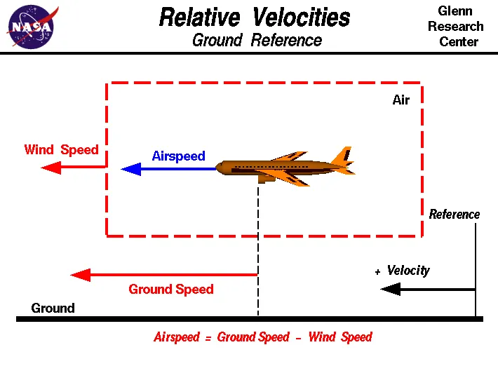
Both airspeed and ground speed are very important. While the first of those helps them make sure they are flying fast enough to take off, not to stall, and so on, the second one helps them figure out how long it will take them to get from one place to another.
- Why is it not recommended to use aircraft engine power to move it on the ground at Airport?
An aircraft either uses taxiing or towing to move on the ground. Taxiing is where the aircraft uses its own power to travel while in towing another vehicle is used to tow the plane. It is recommended that aircraft should not use their engine on ground as it would be hard to manage the high-power engines at high speed on ground which ca cause damage to aircraft and property, as well as the fuel consumption during taxiing would be more compared to towing due to high engine power. And it would be easy to navigate plane through airport with help of tow truck compared to the aircraft itself due to its massive size and restricted vision from cockpit.
- How an aircraft is pushed to runway when its ready to take off?
A so called pushback truck reverses the aircraft into taxiing position, pushing it with a towbar attached to the nosewheel strut. Or, in the most modern versions, by actually lifting the wheel. That speeds up coupling and decoupling.
- Learn about take-off power, tyre design, rolling resistance, tyre pressure, brake forces when landing.
Take-off power
The amount of power that an engine is allowed to produce for a limited period of time for takeoff. The use of takeoff power is usually limited to 5 min for reciprocating engines and up to 2½ min for gas turbine engines.
Tyre design
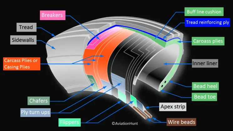
When it comes to safety, tyres are one of the most important components of aircraft. They help to absorb the shock of landing and provide cushioning. It also provides the necessary traction for braking and stopping of an aircraft.
An aircraft tyre is designed to withstand extremely heavy loads while landing, take off, taxing, and parking. The number of wheels required for aircraft increases with the weight of the aircraft, as the weight of the aeroplane needs to be distributed more evenly. Carcass plies are used to form the tire. They are sometimes called casing plies. An aircraft tyre is constructed for the purpose it serves.
- They support the weight of an aircraft while it is on the ground.
- It also provides the necessary traction for braking and stopping of an aeroplane.
- Tyre also helps to absorb the shock of landing and provide cushioning the roughness of take-off, roll-out, and taxi operations.
Rethreading – Rethreading is methods of restoring a worn tyre by renewing the tread area or by renewing the tread area plus one or both sidewalls. Repairs are included in the tyre rethreading process.
Load Rating – Load rating is the maximum permissible load at a specified inflation pressure.
Ply Rating – Ply Rating is used to identify the maximum recommended load rating and inflation pressure for a specified tyre. It is an index of tyre strength.
Speed Rating – The speed rating is the maximum take-off speed to which the tyre has been tested.
Skid Depth – Skid depth is the distance between the tread surface and the deepest groove as measured in the mould.
Aircraft tyres must have an approved speed and load rating and have sufficient clearance when retracted through landing gear to allow for tyre growth. Tyre growth is the increase in the size of the tyre due to centrifugal forces at high speed.
Rolling resistance
Rolling resistance, sometimes called rolling friction or rolling drag, is the force resisting the motion when a body rolls on a surface. It is mainly caused by non-elastic effects; that is, not all the energy needed for deformation of the wheel, roadbed, etc., is recovered when the pressure is removed.
Tyre pressure
Aircraft tires generally operate at high pressures, up to 200 psi (14 bar; 1,400 kPa) for airliners, and even higher for business jets. The main landing gear on the Concorde was typically inflated to 232 psi (16.0 bar), whilst its tail bumper gear tires were as high as 294 psi (20.3 bar).
Brake force when landing
Bringing an aircraft to a safe stop is the most important part of a flight. In order to do this, pilots have a number of facilities available to them.
The brakes bear the brunt of the hard work with the spoilers and reverse thrust lending a helping hand to ensure maximum efficiency. The autobrake system helps keep the deceleration nice and smooth whilst the anti-skid system reduces the distances needed to stop by modulating the brakes on individual wheels and stopping them from skidding.
Aircraft can also depart with part of the braking system not working. By carrying out a performance calculation before every take-off and landing, we ensure that the aircraft will stop safely in the given conditions, even at maximum take-off weight.
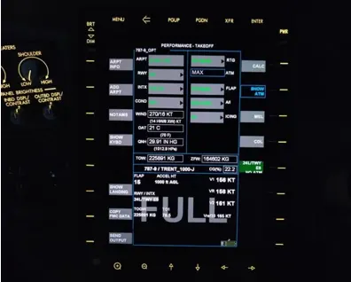
The brake system on the 787 Dreamliner is controlled by the pilots pressing the tops of the rudder pedals under their feet, demanding the rate of braking which they require. This sends an electronic signal to the Left and Right Brake System Control Units (BSCUs).
These then send signals to the four Electronic Brake Actuator Controllers (EBAC) which control the rate of braking on the wheels. Each wheel has four Electric Brake Actuators (EBA), a kind of piston which presses against the carbon brake discs.
To help get the braking underway as soon as plane touch down, we have the autobrake system. This provides automatic braking at a preselected rate as soon as the aircraft senses that it is on the ground. It also provides full braking pressure in the case of a rejected take-off if the speed is above 85 knots (98 mph).
With friction comes heat. As a result, each brake unit displays its temperature on the wheel synoptic page in the flight deck. Here, numerical values relating to brake temperature are shown next to each wheel. A value of 0-4.9 is in the normal range. When a temperature becomes 5.0 or above, an advisory message is displayed to the pilots.
Should the brakes become too hot, there’s a chance that the heat transferred to the wheels could cause the tires to explode. To stop this from happening, when a certain temperature is reached, fuse plugs in the tires melt. This allows the air to be released safely and slowly deflate the tires.
With necessary assumptions, calculate the force and power required to push / pull an aircraft by a towing vehicle.
Lets consider the aircraft to be Boeing 747 whose gross take off mass is 470000kgs.
MA = 470000kg
MT = 2000kg
ROLLING RESISTANCE
Coefficient of rolling resistance (Crr) = 0.002
Rolling resistance force Frr = Cr*m*g
= 0.002*472000*9.81
= 9.26KN
AERODYNAMIC DRAG
Drag coefficient Cd = 0.03
Air density = 1.125kg/m^3
Frontal area (m^2) = 180 (Frontal area estimated for 747 by taking cabin width (6.1 m) times estimated height of body (10 m) and adding double to allow for the frontal area of engines, wings, and tail)
Velocity of aircraft = 6.75 m/s
Air drag force = (1/2) * density * frontal area * velocity^2 * Cd
= 0.138KN
Total resistance = 9.266KN + 0.138KN
= 9.398KN
Required power = total resistance * speed
= 9.398*6.75
= 63.43 KW
Develop the model for the calculated force and power using Simulink.
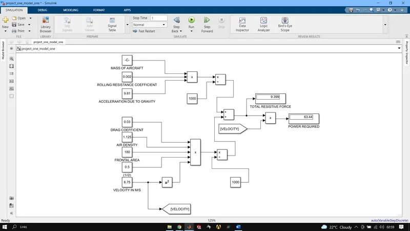
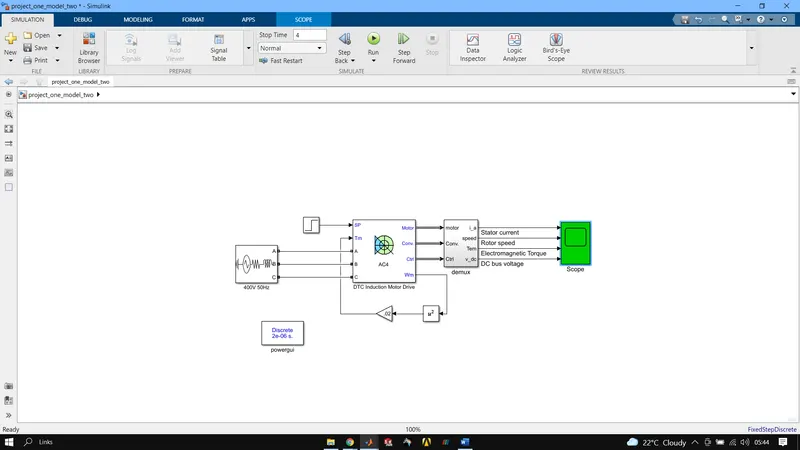
- A. Design an electric powertrain with type of motor, its power rating, and energy requirement to fulfil aircraft towing application in Simulink. Estimate the duty cycle range to control the aircraft speed from zero to highest. Make all required assumptions. Prepare a table of assumed parameters. Draw a block diagram of powertrain.
- Also, Design the parameters in excel sheet.
The motor considered best for the use in an all-electric towing truck based on our power requirement calculation in the previous question.
Vascat - 0/65/65kW x 0/730/1460RPM – Square Frame AC Vector Motor, foot mounting (B3) for 400V 3 phase supply.
200 Frame, Force Ventilated (IC06) to IP23.
Includes force cooling fan, intake filter, Ball bearing at DE and 2048ppr x 15V HTL Encoder.
Use with Closed Loop AC Vector Drives having the encoder board option fitted for full closed loop vector control.
Continuous Output: 65kW.
Overload: 150% to S6 (40%), subject to reduced maximum speed.
Base Speed: 730RPM.
Maximum Speed at Full Output: 1460RPM.
Torque to Base Speed: 850Nm.
Torque at Maximum Speed: 425Nm.
Full Load Current: 124A.
Voltage: 400V 3 Phase.
Supply Frequency: 38/76Hz at Base/Maximum Speed.
Magnetising Current: 51A.
Overall Dimensions: 430mm Wide x 919mm Long x 807mm high overall.
Mounting: Foot mount on 19mm holes at 318mm wide x 458mm centres.
Weight: 455kg.
Rotor Inertia: 0.805kgm2.
Shaft: 65mm diameter x 140mm from shoulder with 18mm wide keyway.
Drive End Bearing: Ball Bearing for a direct connected load.
Bearing Protection: Bearing Current Bypass Brushes fitted to NDE and DE as Standard.
Ambient Temperature: 40C at up to 1000m above sea level.
Cooling: Force Ventilation Fan with Intake Filter fitted at 1.5kW for 400V 3ph 50Hz supply at 2.9A.
Part number: MAC-QI-200M-C61-B3-SBB-2186. (MACQI200M-C61-B3-SBB-2048ppr)
As per the details continuous output of the motor is 65Kw and voltage is 400V.
Let the battery voltage be 600V, now duty cycle is given by Vmotor / Vbattery
Duty cycle = 400/600 = 0.67
As there will be various losses as well so let us consider the correction factor to be 90%.
Which makes the duty cycle = 0.67(1 + 10/100) = 0.74
Hence the voltage should be round about 440V.
Rest all the parameters are same as the previous question.
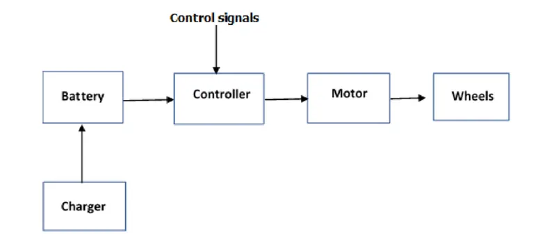
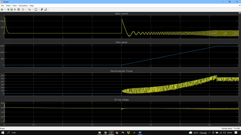
BLOCK DIAGRAM
|
ROLLING RESISTANCE CALCULATION |
BOEING 737 |
||||
|
Aircraft weight (kg) |
470000 |
||||
|
Tow truck weight (kg) |
350 |
||||
|
Coefficient of rolling resistance |
0.002 |
||||
|
ROLLING RESISTANCE FORCE (KN) |
9.228267 |
||||
|
AERODYNAMIC DRAG CALCULATION |
|||||
|
Air density (kg/m3) |
1.225 |
||||
|
Frontal area(m^2) |
180 |
||||
|
Drag coefficient |
0.03 |
||||
|
Speed(mps) |
6.75 |
||||
|
AIR DRAG FORCE (KN) |
0.150697969 |
||||
|
TOTAL TRACTIVE FORCE (KN) |
9.378964969 |
||||
|
POWER AT GIVEN VELOCITY (Kw) |
63.30801354 |
||||
|
MOTOR SPECS |
|||||
|
VOLTAGE |
400V |
||||
|
SPEED |
1486RPM (max) |
||||
|
POWER |
65KW |
||||
|
WEIGHT |
455 KG |
||||
|
|
|||||
|
BATTERY SPECS |
|||||
|
VOLTAGE |
600V |
||||
|
TYPE |
Li-Ion |
||||
|
DUTY CYCLE |
0.9 |
||||