Advanced Sheet Metal Design Using NX Cad Challenge_7_ Metal bracket-II
Project Name: Modeling a Sheet Metal Bracket using Siemens NX CAD Software.
Objective
To create a Sheet metal Bracket using Sheet metal modelling tools. Also write a detailed report on designing Sheet metal Bracket with a good explanation on modelling tools used throughout the modelling.
Introduction
In this project, we are designing a Sheet Metal Bracket using the different modelling tools in Siemens NX CAD software. The sheet metal bracket is designed by using different modelling tools and commands like contour flange, Normal cutout, Break corner, Gussets etc which are discussed below in more detail.
Design methodology
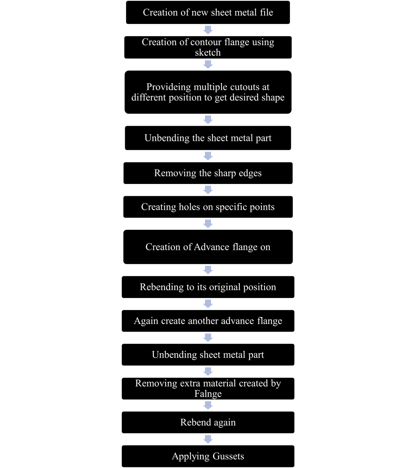
Description
This Sheet metal Bracket designed using different modeling tools of Siemens NX CAD software which are explained below in detail,
· Sketch workbench: The sketch workbench is generally used to make 2D drawing using different features like line, circle, profile, trim, fillet, etc.
· Contour Flange: This command is used to create a thickened sheet up to the given length using a sketch where the profile of that sheet is drawn.
· Normal Cutout: This command is used to remove material from a specific region defined by a sketch.
· Break corner: This command is used to remove sharp edges and create curves of given radius.
· Unbend: This command is generally used to unbend the bended sheet by taking a base and bend surfaces as input.
· Advanced flange: This command is used to create flange with a closed edge by getting inputs like flange length and bend radius.
· Hole: This command is used to create holes by giving some inputs like diameter and the depth of the hole and specific point where the need to be shown.
· Rebend: This command is used to bend again the unbended sheet to its original position.
· Gusset: This command is used to create support structures at bends to improve the strength of the band.
Process of creating Sheet Metal Bracket
· For creating the Sheet Metal Bracket first, we create a new sheet metal file and after that change the sheet metal preference. Where change material thickness, bend radius, relief depth and relief width to 3mm and start designing the part.
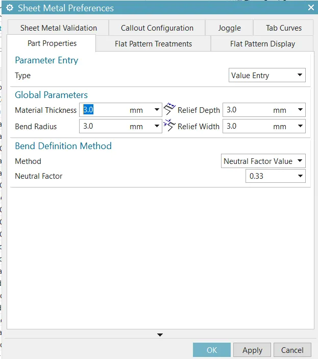
Figure 1 Sheet metal preferences
· After giving preferences to the file, we start drawing in the sketch workbench on XZ plane to create a sheet using Contour flange command as shown below.
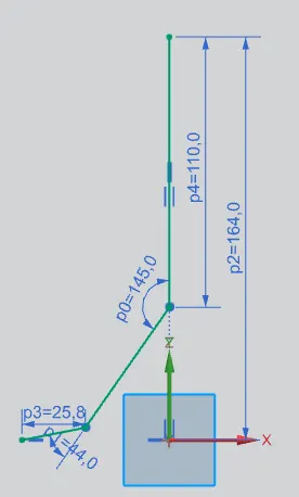
Figure 2 Sketch 1
The above shown profile is drawn with the help of Profile command in the Sketch Workbench and the sketch is fully constrained using Rapid Dimension command. After completion of the drawing, we just click on finish button to finish the sketch.
· After Finishing the sketch, we use this profile as input to create a sheet of 158mm length and 3mm thick as shown below by the help of Contour Flange command.
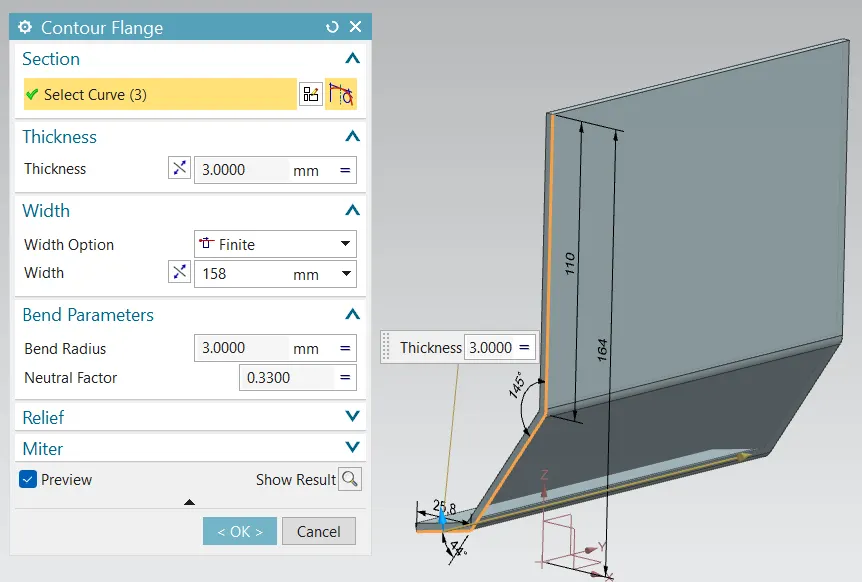
Figure 3 Sheet creation using Contour flange command
· After creating the sheet, we draw another sketch on the YZ plane.
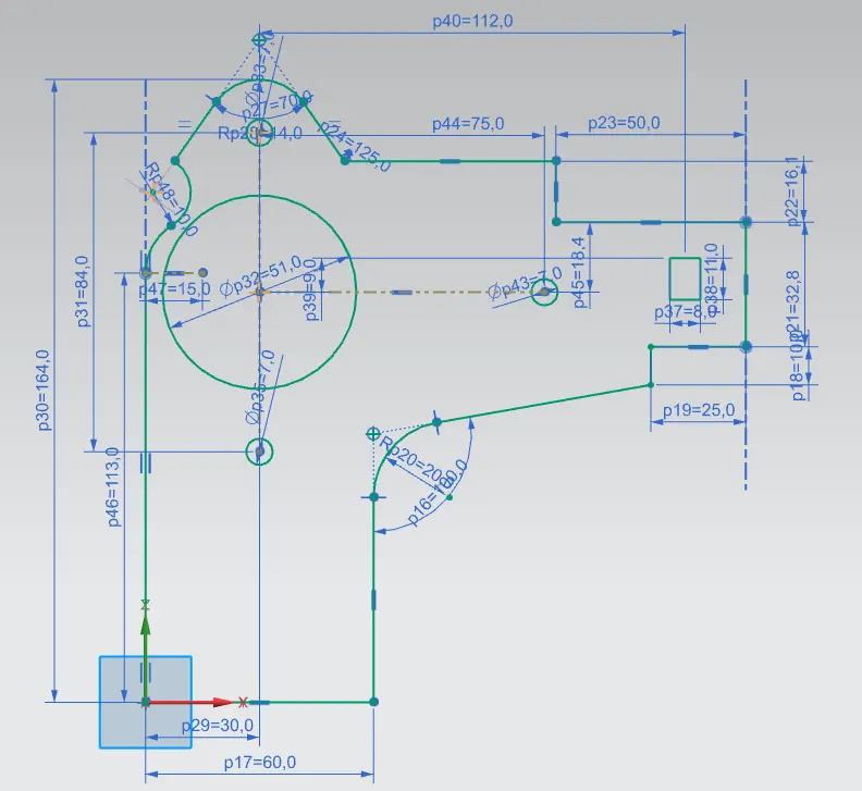
Figure 4 sketch 2
· After finishing the sketch, we unwanted material by cutting out extra portion with the help of the above sketch and Normal cutout command. The material is removed in some steps as shown below,
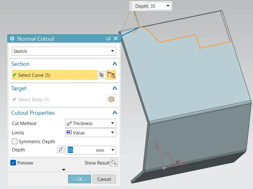
Figure 5 Cutout 1
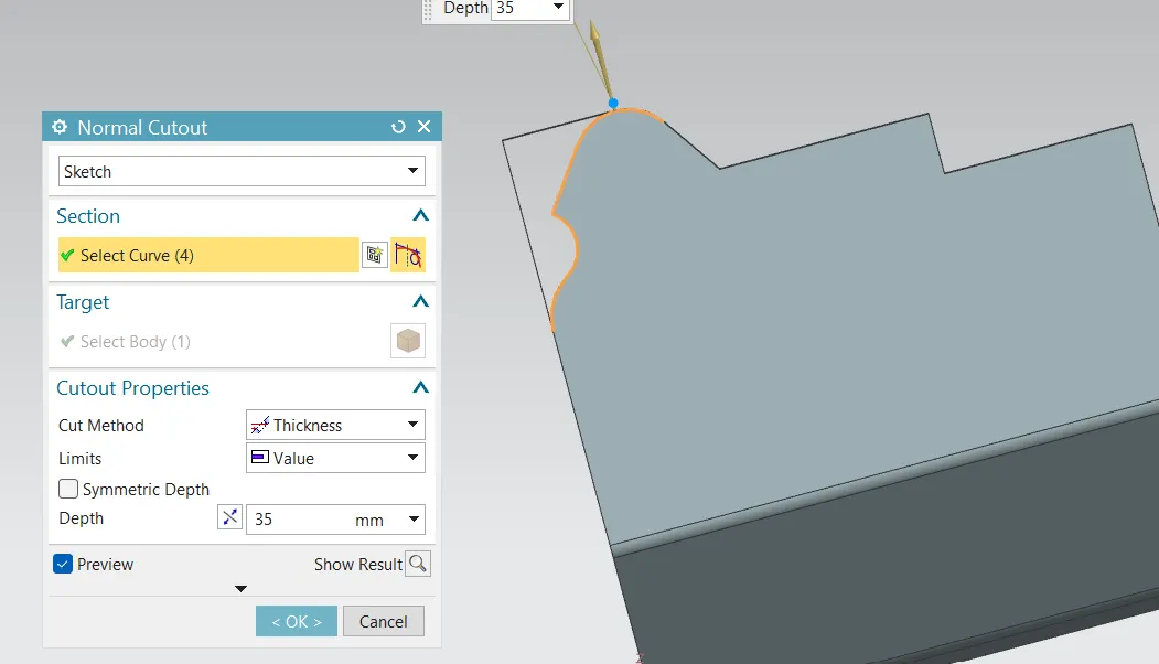
Figure 6 Cutout 2
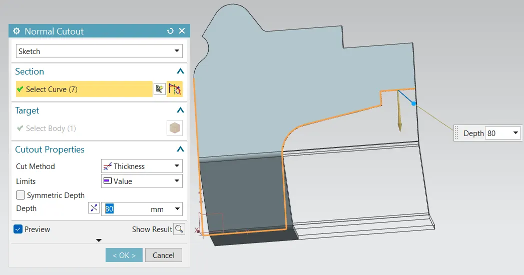
Figure 7 Cutout 3
After this we remove material from inner side using the sketch shown above,
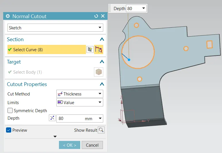
Figure 8 Cutout 4
· After the cutouts we repared the sharp corners at different radius using break corner command. In shown below there are different corners repaired by providing different radii to the curves.
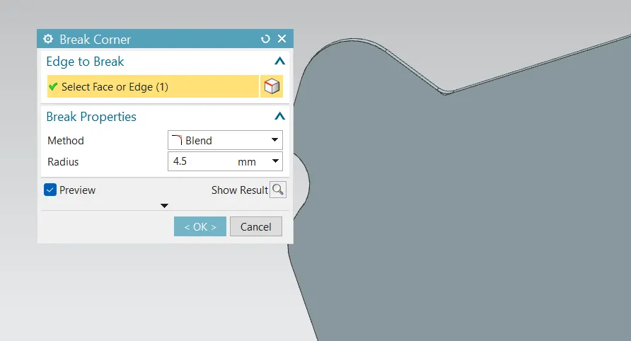
Figure 9 Removed sharp corners1
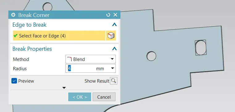
Figure 10 Removed sharp corners2
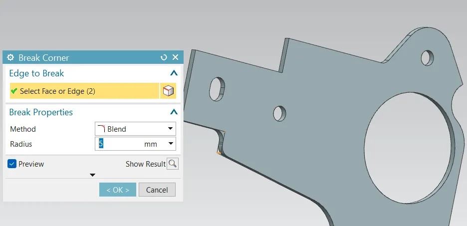
Figure 11 Removed sharp corners3
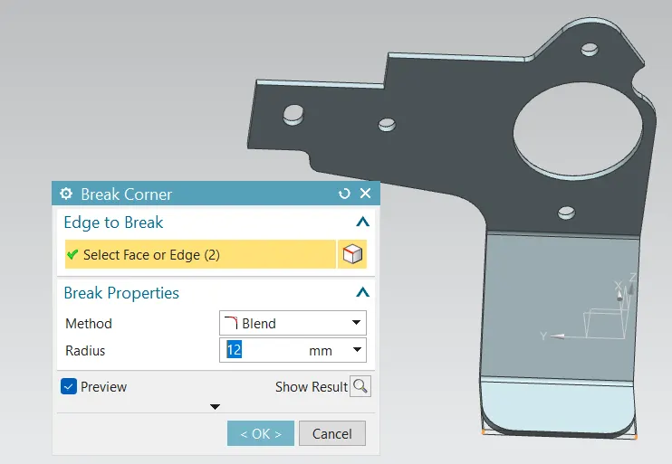
Figure 12 Removed sharp corners4
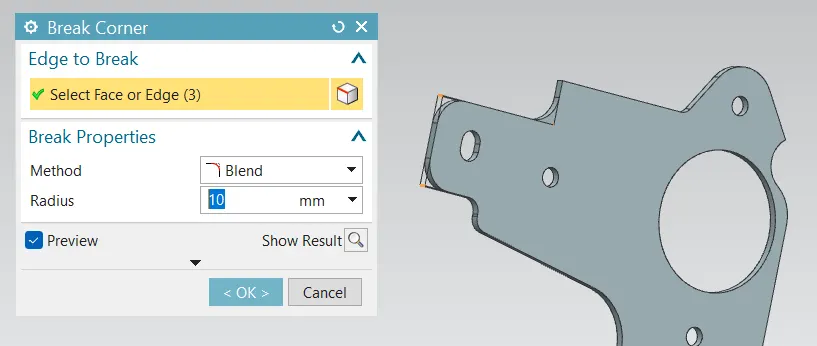
Figure 13 Removed sharp corner5
· After reparing all sharp corners, we create a Flange at top of the part using Advanced flange command with a flange length of 5mm.
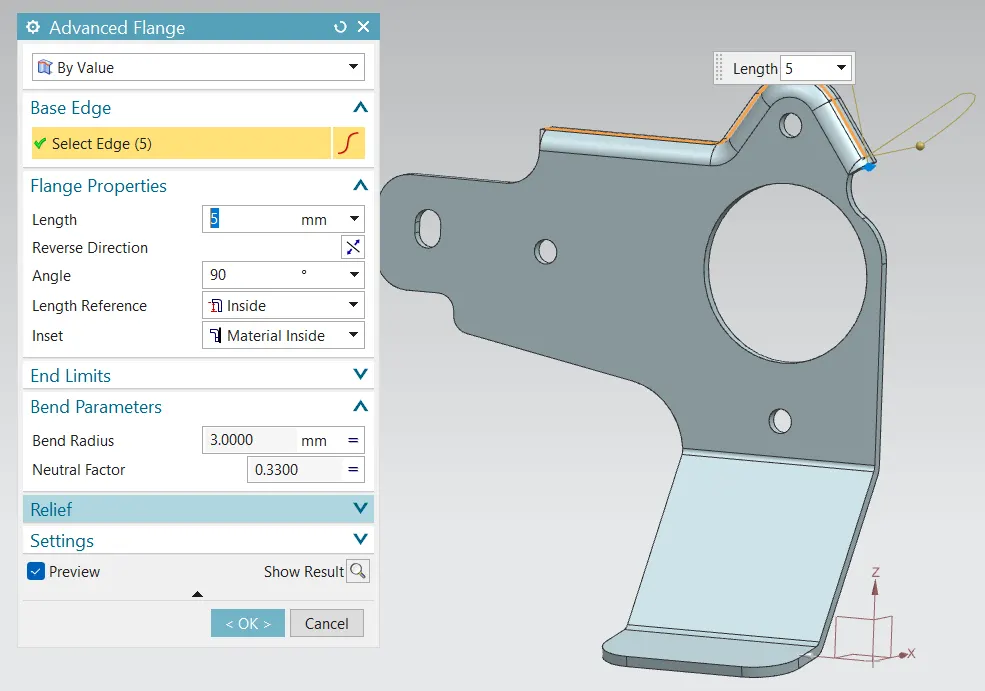
Figure 14 Flange creation using Advanced flange command
· After creatingthe flange, we unbend the sheet metal part using Unbend command to and some other features.
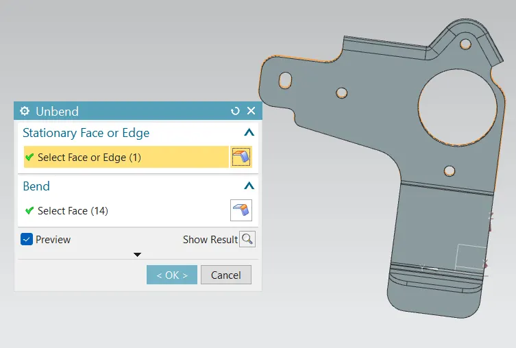
Figure 15 Unbending sheet metal part
· After unbending the part, we removed a sharp corner created due to flange using Normal Cutout command as shown below.
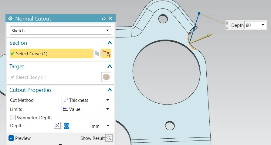
Figure 16 Sharp corner removing
· After removing the shrp corner we create some holes of different Diameter using hole command as shown below.
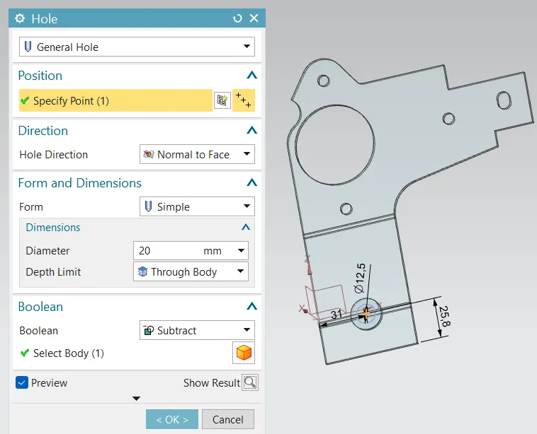
Figure 17 Hole of 12.50mm diameter
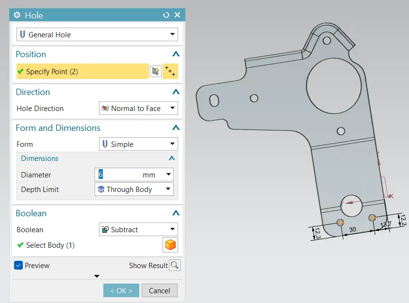
Figure 18 Holes of 6mm Diameter
· After creating the hole we create a cutout using Normal Cutout command with the help of a sketch as shown below.
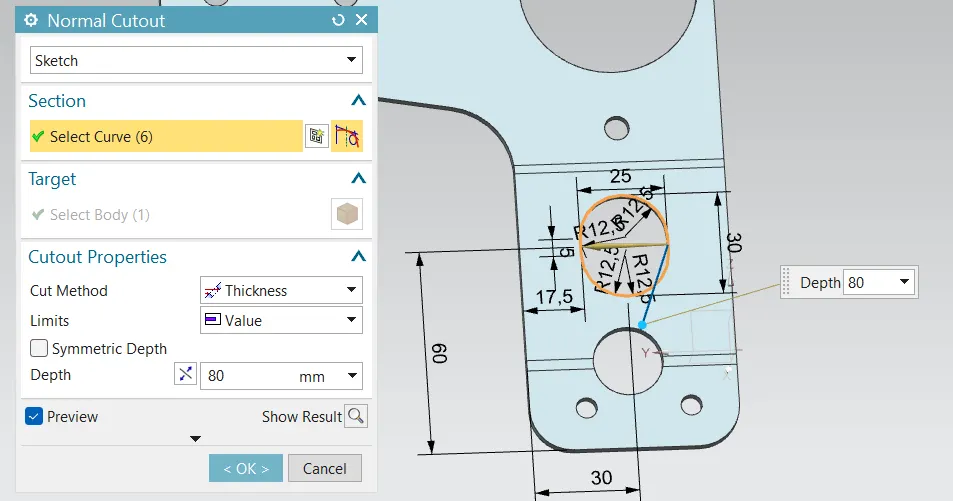
Figure 19 Cutout using Normal cutout command
· After the cutout we create a flange on the inner edge of the cutout using Advanced Flange command with 4mm length.
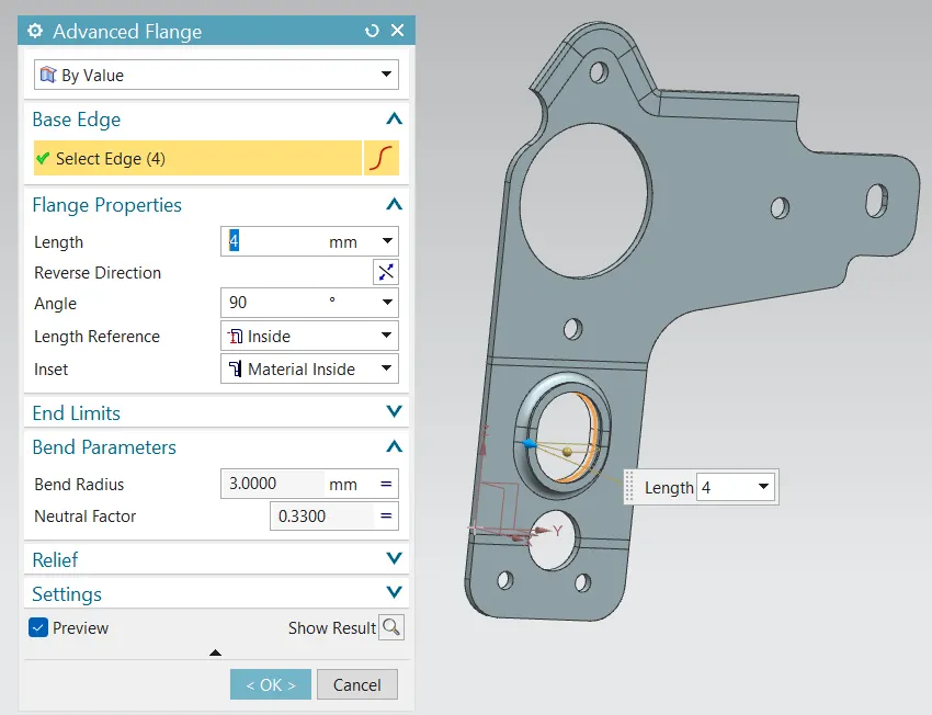
Figure 20 Flange creation using Advanced Flange command
· After creating the Flange we Rebend the part to its original position using Rebend command.
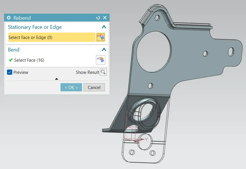
Figure 21 Rebend
· After rebending the part we create Gussets on the bends to improve the strength and stability of the part as shown below. For creation of Gusset we use Gusset command.
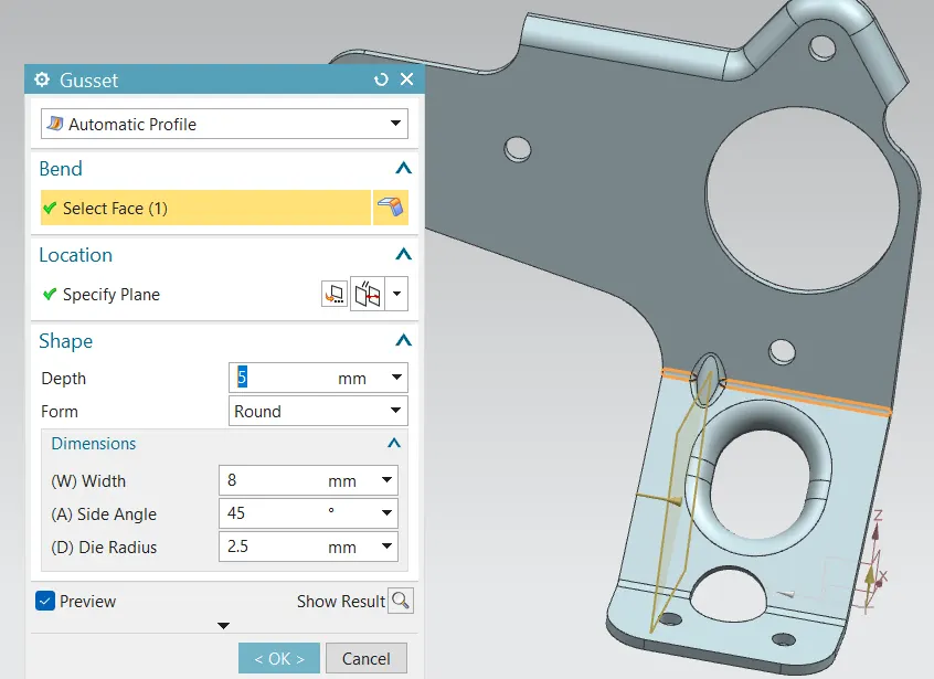
Figure 22 Gusset creation
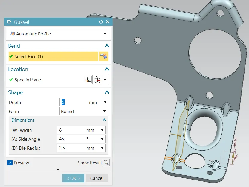
Figure 23 Gusset creation at all required places
· After completing the gusset creation we oped the drafting workbench and create the drafting sheet for this part as shown below.
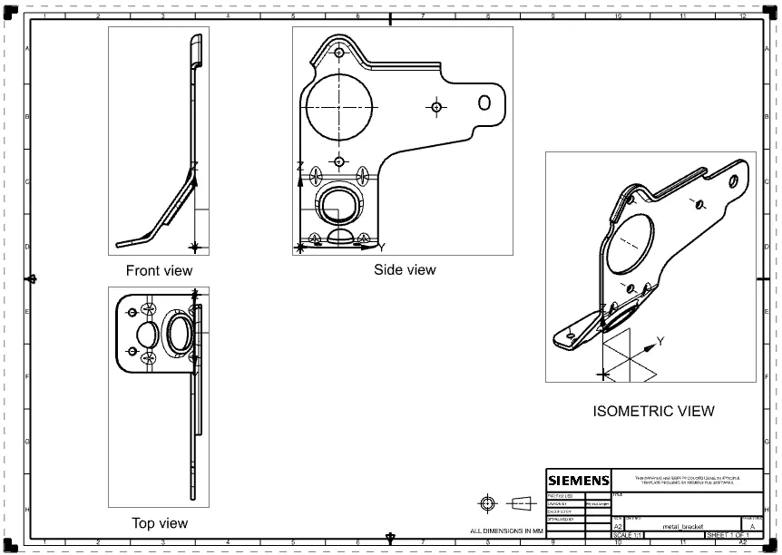
Figure 24 Drawing/Drafting sheet
This Drawing/Drafting sheet is used by manufacturer to read the data needed to create the part. In the NX Cad software the drafting sheet is created in the draft workbench where we first, need to define size of the sheet on which we need the drawing then we import the part views in the drafting workbench from the sheet metal workbench.
· After completing the part we also take a screenshot of the part navigator window which is as shown below,
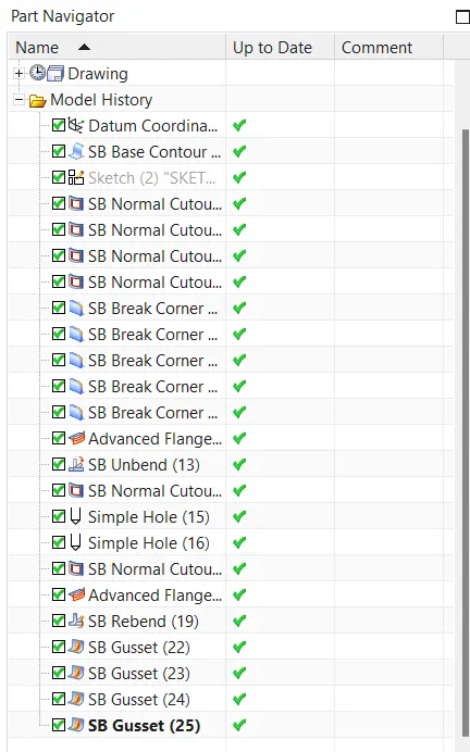
Figure 25 Part Navigator
Isometric view
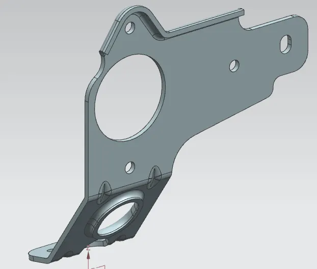
Figure 26 Isometric view
Front view
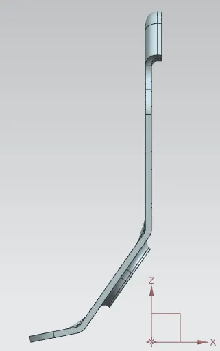
Figure 27 Front view
Side View
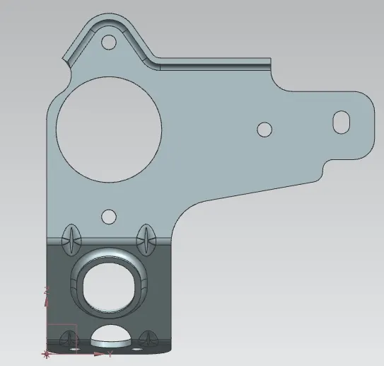
Figure 28 Side view
Top View
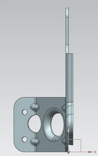
Figure 29 Top view
Conclusion
We had created the Sheet Metal Bracket using different modelling tools of Siemens NX CAD software and also made a detailed report of whole process of part design and the command used in it.