Advanced Sheet Metal Design Using NX Cad Challenge_7_ Metal bracket-II
OBJECTIVE:
To design and model the sheet metal bracket II from 2D Sketch in sheet metal workbench of NX CAD.
INTRODUCTION:-
Sheet metal Design and Fabrication:-
- Sheet Metal Fabrication is the process of forming parts from a metal sheet by punching, cutting, stamping, and bending.
- 3D CAD files are converted into machine code, which controls a machine to precisely cut and forms the sheets into the final part.
- Sheet metal parts are known for their durability, which makes them great for end-use applications (e.g. chassis). Parts used for low volume prototypes and high volume production runs are most cost-effective due to large initial setup and material costs.
Because parts are formed from a single sheet of metal, designs must maintain a uniform thickness. Be sure to follow the design requirements and tolerances to ensure parts fall closer to design intent and cutting sheets of metal.
Design Methodology:
2D sketch with different views is obtained
Make simple guide sketch and contour flange
Add features like normal cut out, Break corner
Unbend to add more features
Rebend the areas and add more advanced flanges
Add gussets and create flat pattern
Description:
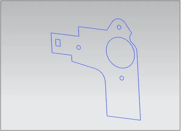
Sketch:
A profile of the required shape of the metal bracket in the YZ plane is created.
Contour flange:
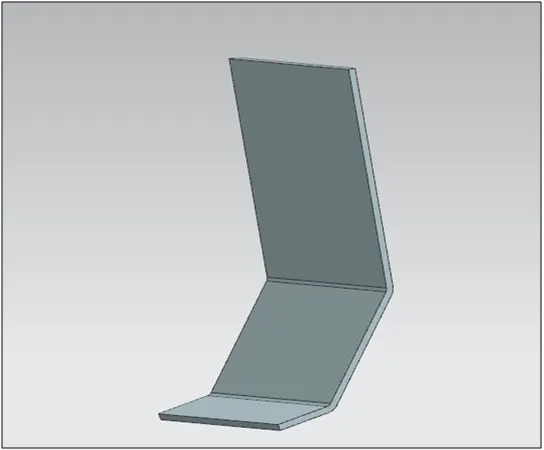
In Siemens NX sheet metal contour flange command used to create a base feature by extruding a sketch along a vector, or adds material by sweeping a sketch along an edge or chain of edge.
Normal Cut Out:
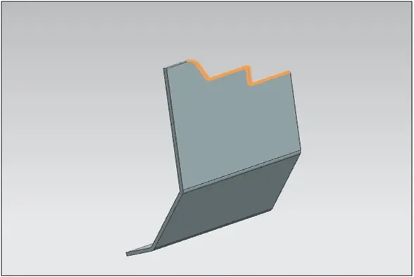
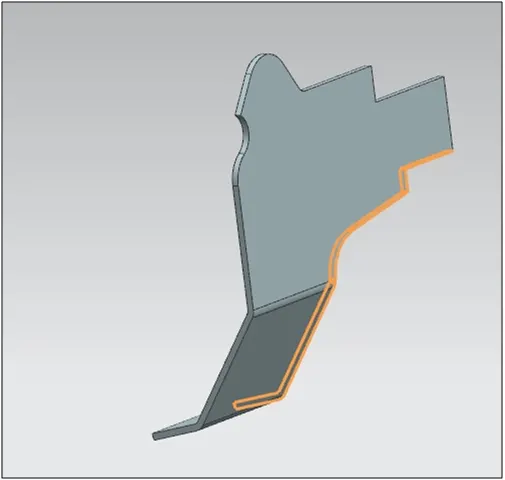
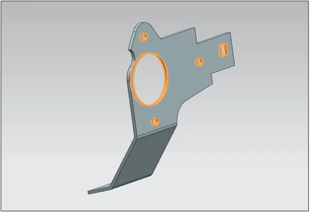
It is the type of cut out which is mainly preferred in sheet metal design. The advantage this type of cut out has over the extrude cut out is that normal cut out removes the material perpendicular to the surface of our model rather than plane.
First the sketch is generated. The Sketch has already been created in the YZ plane and using the normal cut out the material is removed from the part.
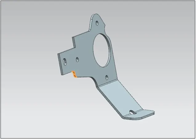
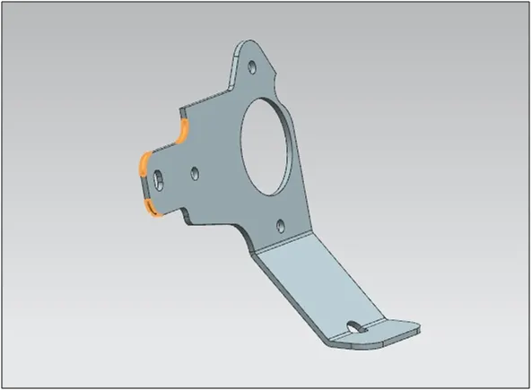
Break Corner:
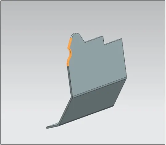
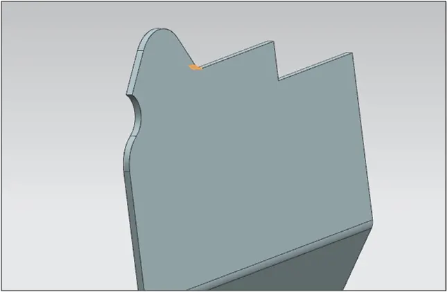
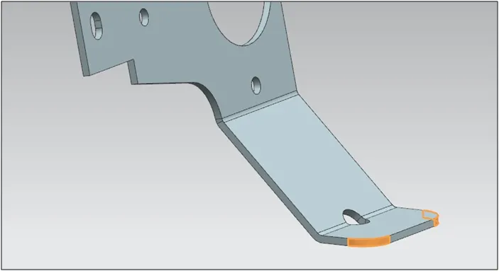
This feature is used to smooth the harmful corner of the sheet or to give an attractive look to the part.
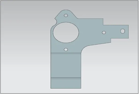
Unbend:
This feature is used to flatten the sheet metal part for further design operations. Moreover it also helps to check whether the part is a sheet metal or not. If the part is unbending then it is a sheet metal otherwise it is still a solid body or dumb body.
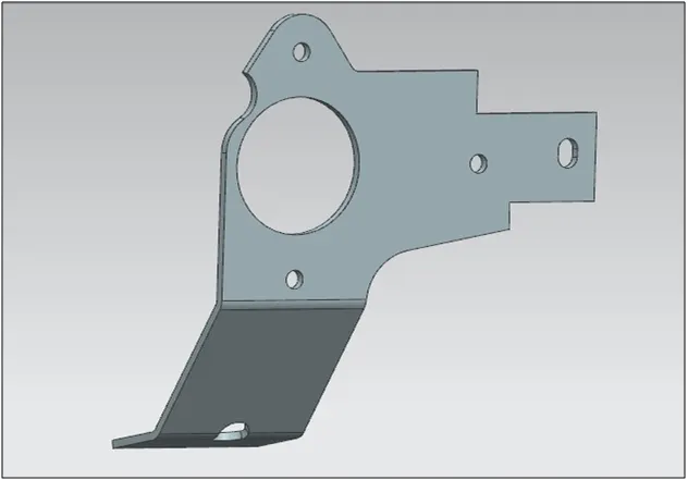
Rebend:
After creation of additional features the part is rebend back to get our required product.
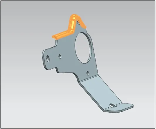
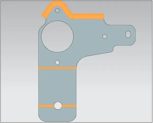
Advanced Flange:
This command is used to add a flange along an edge using a bend angle or a reference face. The edge and reference face can be curved. This command is useful when we want to create non-linear flanges, or when we work with sheet metal support structures in complex assemblies. We can use existing geometry as a reference to define the flange dimensions.
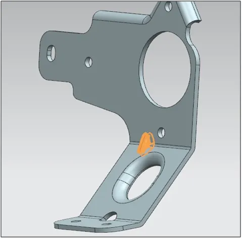
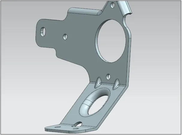
Gussets:
Gussets are the strength stiffening features. They add strength and stiffness to the sheet metal parts. The face and the plane is selected for the gussets to be created and the profile is generated. The profile can be automatically generated or the sketch can be created.
Flat Pattern:
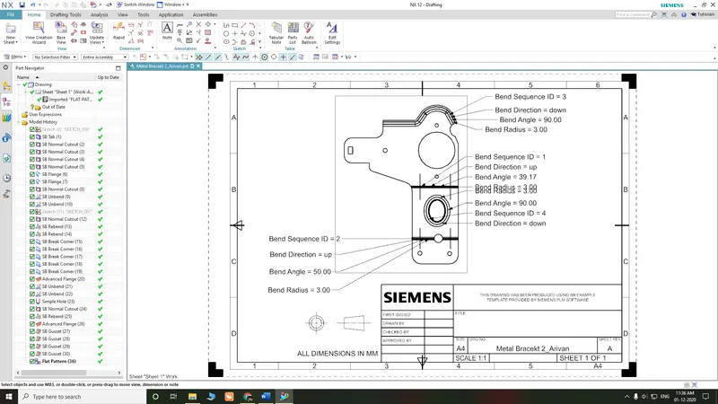
This feature is used to create an instance of the flat shape and size of the sheet metal that required in creating final part.
CONCLUSION:
- This project helped me to understand how to convert a 2d Sketch into a 3D sketch.
- Got a good understanding of features like gussets, holes, and advanced flanges.
The creation of flat pattern view, bend table and the addition of flat pattern view in drawing sheet.