Advanced Sheet Metal Design Using NX Cad Challenge_7_ Metal bracket-II
Objective
- Design a sheet metal bracket by adding features concerning the input data and following the industrial design methodologies for manufacturing a sheet metal component.
Introduction
- Sheet metal is any metal with a thickness of between 0.4 to 6 mm and can be obtained by any metal rolling process method (cold rolled and hot rolled). Sheet metal is widely used in industries like automobiles, aerospace, electronic appliance, medicine, construction, furniture, etc. To fully utilize sheet metal, we must understand standard measurements, materials, differences in manufacturing, possible forming methods and the material properties.
- Sheet metal fabrication is the process of forming metal sheets to the desired shape using different manufacturing methods.
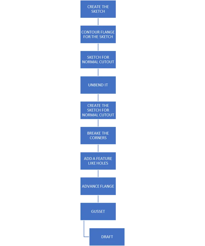
DESIGN METHODOLOGY
- Sketch – drawing a contour flange sketch on the XY plane
- Contour flange – contour sketch, thickness = 3mm, width = 158mm
- Sketch – desired bracket drawing is sketched on the face of the contour flange
- Normal cutout – bracket sketch is selected and the cutout is given for a depth of 120mm
- Sketch – sketching the required holes on the bracket
- Normal cutout – holes are selected and the cutout is given for a depth of 60mm
- Break corner – radius = 4.5mm and 4mm
- Unbend
- Sketch – sketching the holes on the bend
- Normal cutout – depth = 36mm
- Re bend
- Break corner – radius = 12mm
- Break corner – radius = 5mm
- Break corner – radius = 10mm
- Advanced flange – length = 5mm, angle = 90 degree, bend radius = 3mm
- Unbend
- Hole – M6
- Normal cutout – depth = 5mm
- Advanced flange – length = 4mm, angle = 90 degree, bend radius = 3mm
- Re bend
- Gusset – form = round, depth = 5mm, width = 8mm, side angle = 45 degree, die radius = 2.5mm, no’s = 4
- Drafting
TOOL AND FEATURE DESCRIPTION
- SKETCH
It is a 2d representation of a 3d part. It includes entities like lines, rectangles, splines, circles, etc. It is a predetermined drawing with dimensions and relations.
- CONTOUR FLANGE
It is created with one or more edges at the specified locations. The minimum flange length must be at least four times the thickness of the sheet metal. The bend radius is equal to the sheet metal thickness.
3. NORMAL CUTOUT
This command is to remove the desired shape of the material. A removal sketch can be drawn on the sheet metal face, wherever required.
4. BREAK CORNER
This command gives a smooth finish over the corners of the sheet metal part.
5. UNBEND
It makes the part unbend, that is all the features are made flat. This is useful while sketching on the corners and bend areas.
6. HOLE
This feature makes the required types of holes like general, drill, screw clearance, threaded and series of holes.
7. ADVANCED FLANGE
This feature adds flange along the curves at specified reference and angle.
8. REBEND
This command puts back all the bends already created also along with new features included while in an unbent state.
FRONT VIEW
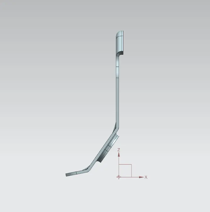
TOP VIEW
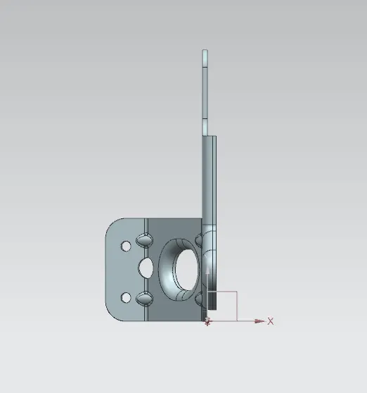
LIFT VIEW
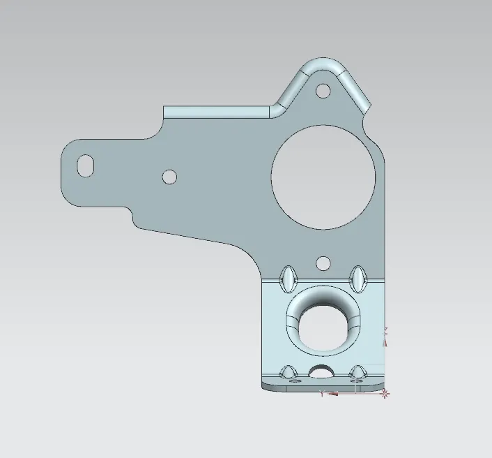
RIGHT VIEW
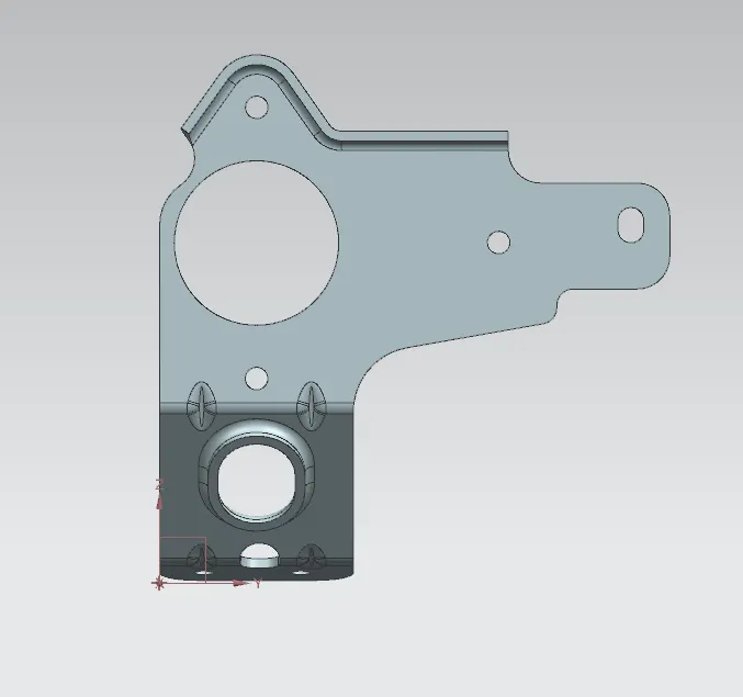
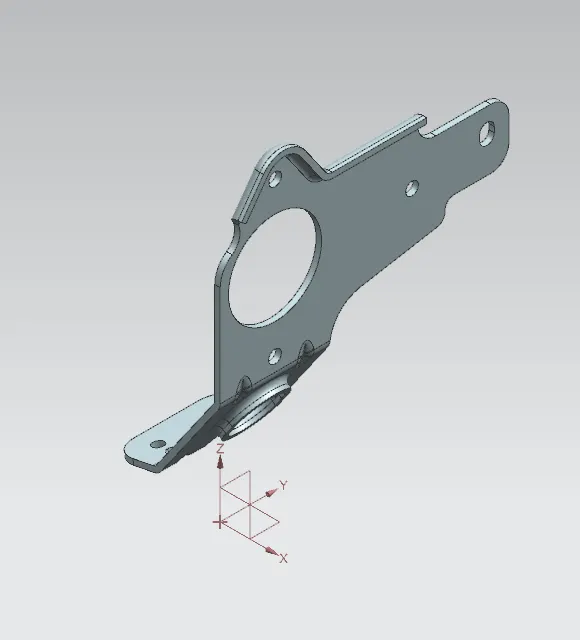
ISOMETRIC VIEW
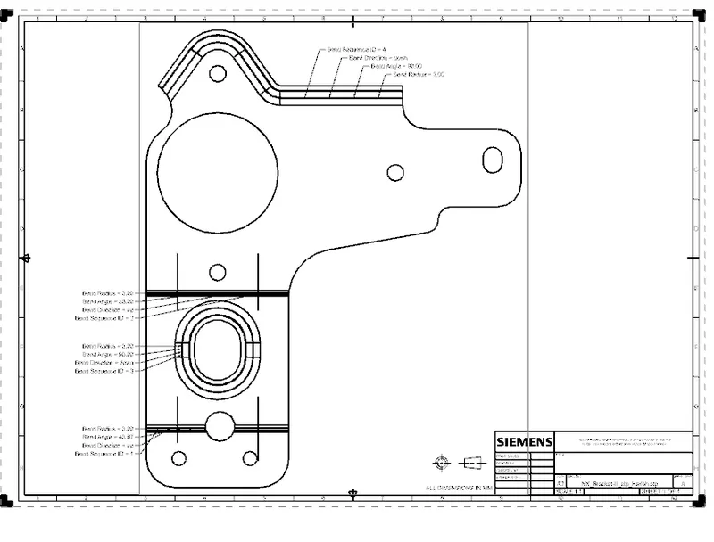
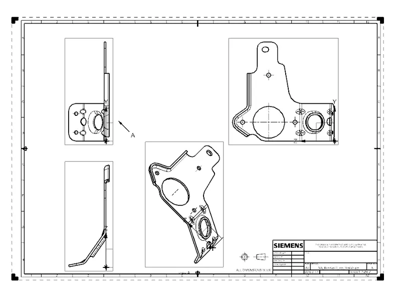
DRAFT
Conclusion
Thus an easy-to-manufacture, cost-effective and very functional sheet metal bracket was designed with features by following the design guidelines and manufacturing methodologies.